Section 9
High Pressure Water System
20412997
8-2012/Rev 12
9-39
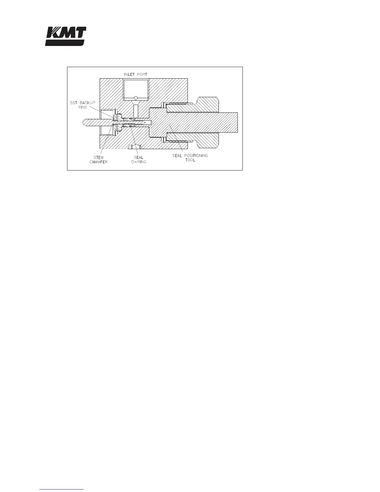
Figure 9-31: Valve Stem Placement
18. Remove the high pressure bushing and the seal positioning tool.
19. Apply Pure Goop anti-seize compound to the threads of the actuator and carefully thread it
into the valve body, guiding the stem head into the hole in the actuator. Turn the actuator
clockwise until resistance is felt. Reverse the actuator 1/4-turn, and give it a quick spin
clockwise to seat it. Hand-tighten only, 5 ft-lbs (7 Nm).
20. Apply Pure Goop anti-seize compound to all surfaces, except the ID, of a new valve seat.
Install the seat into the opposite end of the valve body, inserting the small OD first.
21. Apply anti-seize compound to the threads on the high pressure bushing, and on the back
side of the adapter cone. Position the adapter cone in the bushing, install the bushing and
torque to 50 ft-lbs (68 Nm).
22. Replace the 1/4-inch gland nut and collar and torque to 25 ft-lbs (34 Nm).
23. Apply anti-seize compound to the threads on the 3/8-inch high pressure gland fitting.
Install the collar and the gland fitting and torque to 50 ft-lbs (68 Nm).
24. Install the air supply hose and the electrical connection to the solenoid valve. Turn the air
pressure to the actuator on and test the valve for leaks and proper operation.
 Loading...