Section 7
Hydraulic System
20412971
8-2012/Rev 08
7-14
8. Remove the bolts that attach the hydraulic pump to the electric motor.
9. Support the hydraulic pump and slide it away from the motor, disengaging the flexible
coupling.
10. Inspect the flexible coupling for damage. If the flexible coupling is damaged it must be
replaced.
11. Inspect the metal splines on the motor coupling half. Wipe any residue, dirt or oil from
the motor coupling and the flexible coupling. Place the flexible coupling on the motor
coupling half, pushing it on as far as it will go.
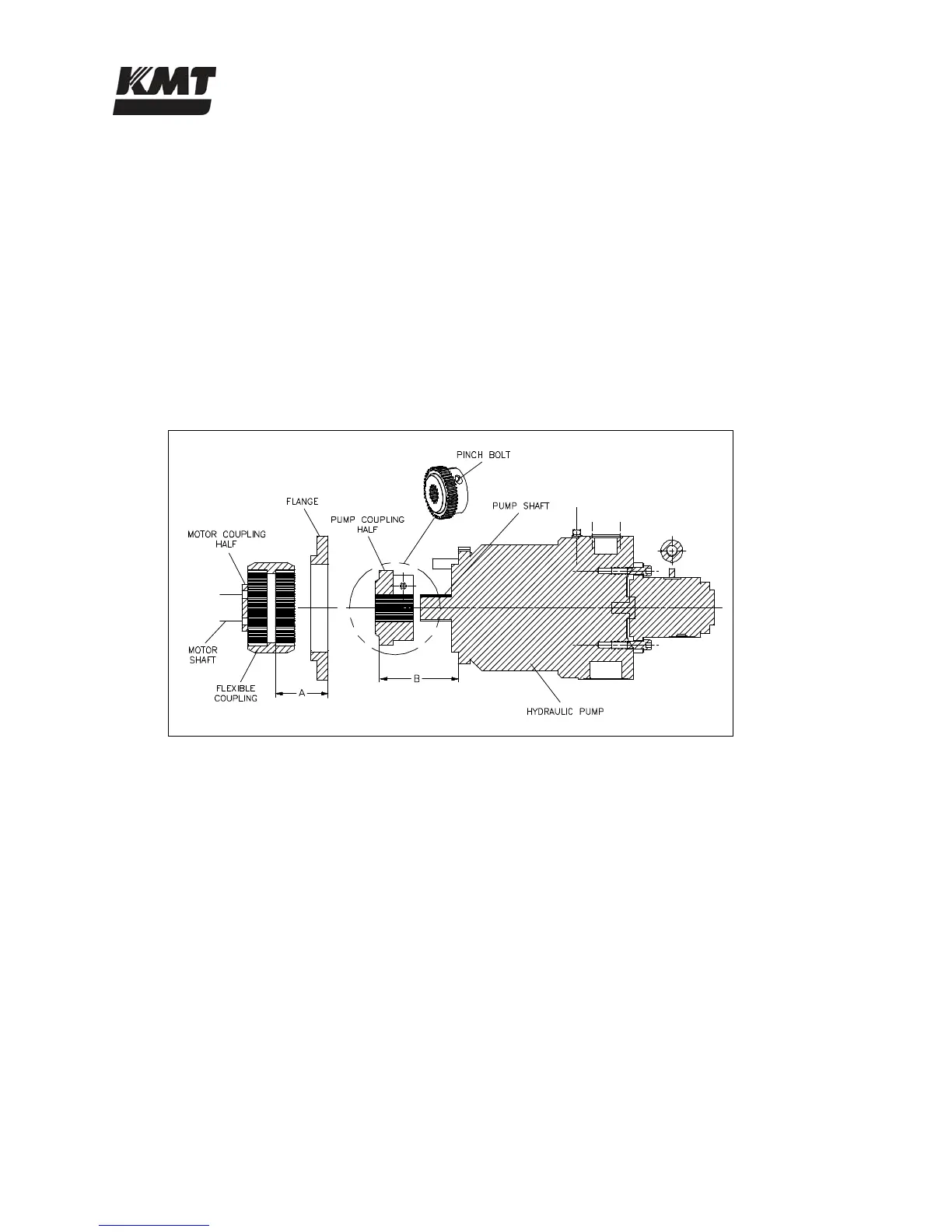
12. Take a measurement from the front face of the electric motor, the pump mounting
interface, to the outer face of the snap ring or solid band on the flexible coupling,
dimension A.
Figure 7-10: Pump Coupling Dimensions
From dimension A, subtract 5/16 inch for 30, 50 and 60 horsepower motors, and 1/4 inch
for 100 horsepower motors.
13. Loosen the pinch bolt in the pump coupling half on the old pump and remove the coupling
half. Inspect the metal splines for damage. If the coupling half is not damaged it can be
reused on the new pump.
14. Wipe any residue, dirt or oil from the pump coupling half. Slide the existing coupling
half, or a new coupling half if necessary, onto the splined shaft of the new pump.
15. Set the position of the pump coupling half by measuring from the pump mounting face to
the outer face of the coupling teeth, dimension B. On 30, 50 and 60 horsepower models,
B = (A - 0.313), on 100 horsepower models B = (A - 0.250).
16. Tighten the pinch bolt and torque to 36 ft-lbs (49 Nm) for 30 horsepower models, 63 ft-lbs
(86 Nm) for 50 and 60 horsepower models, and 218 ft-lbs (295 Nm) for 100 horsepower
models.
17. Place the hydraulic pump on the motor, ensuring the coupling teeth mesh into the flexible
coupling. Force should not be required.
 Loading...