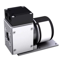
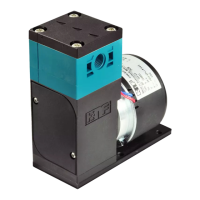
Installation and connection Diaphragm pump N96
18 Translation of Original Operating and Installation Instruction, English, KNF 316836-316838 01/20
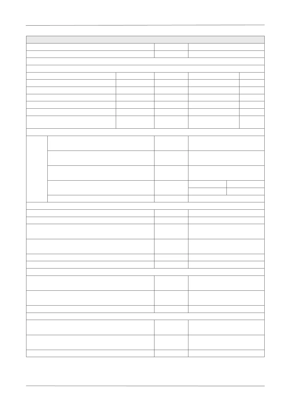
Connection diagram for motor controller
Motor
Rated voltage [V] 24
Voltage range [V] 9 – 26.4
Coupling: Hirose DF3-6S-2C
Leads connections / PIN assignment
Function Wire lead color Signal name Size PIN
+ Supply voltage Red U
+
AWG 26 / UL 3266 6
- Supply voltage (0 V) Black U
-
/ GND AWG 26 / UL 3266 1
Input signal for speed control Blue U
Ctrl
AWG 26 / UL 3266 3
Output signal for speed Green U
Spd
AWG 26 / UL 3266 4
Input signal for remote ON/OFF White U
Rmt
AWG 26 / UL 3266 2
Input signal for direction of motor rota-
tion
Yellow U
Rot
AWG 26 / UL 3266 5
Input signal for speed specification Uctrl PWM signal*
PWM-
signal
PWM frequency range [kHz] 20
[10 … 30]
Input level "high" [V] 5
[2.5…5.5]
Input level "low" [V] 0
[0…0.8]
Duty cycle range, see Fig. 10, Fig. 11 [%] KN KT
30…0 55…0
Input impedance @ 1 kHz [kΩ] ≥ 10
Output signal for speed USpd
Pulses per revolution [-] 6
Pulse duty cycle [%] 50
Output level "high" [V] 5
[2.5…6.0]
Output level "low" [V] 0
[0…0.8]
Max. current carrying capacity [mA] 2
Input impedance @ 1 kHz [kΩ] ≥ 10
Input signal for remote ON/OFF URmt
Input level "high" → Motor ON [V] 5
[2.5…5.5 or open contact]
Input level "low" → Motor OFF [V] 0
[0…0.8]
Input impedance @ 1 kHz [kΩ] ≥ 10
Input signal for direction of motor rotation URot
Standard for pump
Input level "high" → Motor CCW
[V] 5
[2.5…5.5 or open contact]
Not recommended for pump
Input level "low" → Motor CW
[V] 0
[0…0.8]
Input impedance @ 1 kHz [kΩ] ≥ 10
Tab.23 Connection diagram for motor controller N96_DC-B-M
*see Chapter 8.3 Control functions DC-B-M