Diaphragm liquid pump NF 100 Servicing
KNF Flodos BA_NF100_EN_10_067676.docx
Translation of original Operating and Installation Instructions 26
8.2.3. Disassembling the pump head
Loosen the four head screws (1) and remove the whole head.
Take the valve plate (6) out of the intermediate plate (7).
Remove the resonating diaphragm (3), or resonating dia-
phragm.27 (15), if fitted diaphragm.27 (14) and pressure
spring.27 (13) from the connecting plate (5).
Remove O-ring (4) from head plate (2) or (12).
Carefully grip the diaphragm (8) and remove by turning anti-
clockwise. Remove the washers (9) and make sure that no
washers 9 fall into the pump housing.
We recommend replacing the diaphragm (8).
8.2.4. Clean or replace parts
Clean the diaphragm (8), O-Ring (4), resonating diaphragm
(3), or resonating diaphragm.27 (15), if fitted diaphragm.27
(14), valve plate(6), intermediate plate (7) and connecting plate
(5) with a cloth and then blow off with compressed air or re-
place.
8.2.5. Assembling the pump head
Place the same number of washers on the connecting rod (9)
as were there previously. Make sure that no washers (9) fall in-
to the pump housing.
Screw in the diaphragm (8). By lightly pressing on the dia-
phragm push the ridge on the underside of the diaphragm into
the groove of the housing.
Place the "dust free“ valve plate(6) into the intermediate plate
(7), making sure it is in the correct position.
The method of assembly which follows will differ according to
the pump type used. For this reason, please proceed with the
section (NF 100 and NFB 100 versions or NF 100.27 ver-
sion) that corresponds to the pump type you are using.
NF 100 and NF 100 versions
Insert the resonating diaphragm (3) in the connecting plate (5)
and cover with the head plate (2) fitted with a new O-ring (4).
The positions of the intermediate plate (7), the connecting plate
(5) and the head plate (2) with respect to one another are de-
termined by the arrangement of the visible grooves.
Insert the four head screws (1) in the through holes of the
pump head.
Make sure that the flow direction of the pump head (see direc-
tional arrow on the head plate (2)) is the same as previously.
Place the pump head onto the pump housing and alternately
tighten the four head screws (1). The maximum tightening
torque is 2.5 Nm.
Reconnect the hoses to the pump head.
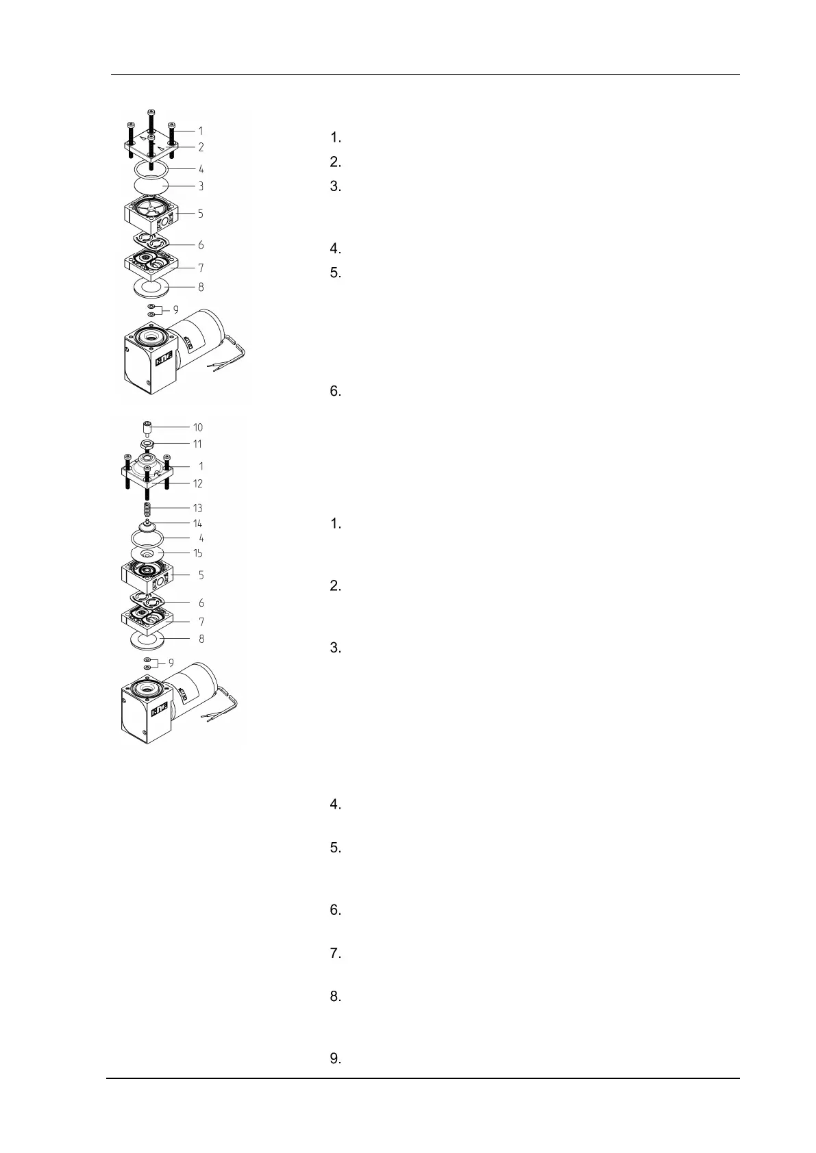
Fig. 20:
NF 100
Fig. 21:
NF 100 .27
1 Head screw
2 Head plate
3 Resonating diaphragm
4 O-Ring
5 Connecting plate
6 Valve plate
7 Intermediate plate
8 Diaphragm
9 Washer
10 Setscrew
11 Hexagon nut
12 Head plate.27
13 Pressure spring.27
14 Diaphragm.27
15 Resonating diaphragm.27