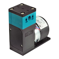
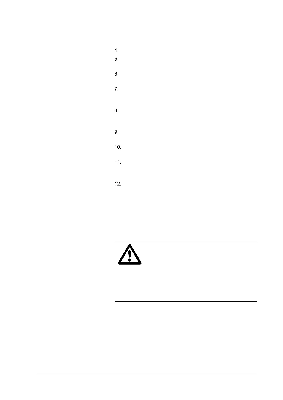
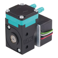
Diaphragm liquid pump NF 100 Servicing
KNF Flodos BA_NF100_EN_10_067676.docx
Translation of original Operating and Installation Instructions 27
NF 100.27 version
Insert resonating diaphragm.27 (15) in the connecting plate (5).
Place the diaphragm.27 (14) centrally on the resonating dia-
phragm.27 (15).
Place the compression spring.27 (13) over the thread of the
diaphragm.27 (14).
Carefully place head plate.27 (12) with fitted new O-ring (4),
screwed-in setscrew (10) and hexagon nut (11) over the whole
unit.
The positions of the intermediate plate (7), the connecting plate
(5) and head plate.27(12) with respect to one another are de-
termined by the arrangement of the visible grooves.
Insert the four head screws (1) in the through holes of the
pump head.
Make sure that the flow direction of the pump head (see direc-
tional arrow on head plate.27 (12)) is the same as previously.
Place the pump head onto the pump housing and alternately
tighten the four head screws (1). The maximum tightening
torque is 2.5 Nm.
Reconnect the hoses to the pump head.
The activities described above should not alter the set pres-
sure of the overflow valve. If it is found that the setting has
changed after assembly, the value can be readjusted within the
permissible range of the pump in accordance with the instruc-
tions in Chapter 8.3, if necessary readjusting the peripheral in-
stallations.
CAUTION
Escaping liquid
After assembly the pump may not be leak-tight due
to incorrect assembly, damaged or soiled seal faces,
or other reasons.
Run pump for several minutes with a harmless
liquid at maximum operating pressure.
Check that pump is leak-tight