KIMA00H1 (0204)
37
6.6
(cont.)
b. The system lube oil capacity is:
Lubrication
MODEL KNW: A00-A A00-B A00-C A00-D A00-E
CAPACITY: 12 QUARTS 15 QUARTS
TABLE 4: LUBE OIL CAPACITY
c. The oil level viewed on the sight gauge will vary when the
compressor is operating. Fill the sump to the upper limit of the
gauge, then run the compressor. Stop the unit and add oil as
necessary to maintain the oil level near the center of the sight
gauge.
d. The oil pressure is controlled by the relief valve located on the
discharge of the oil pump. The adjusting cap is held in position with
a lock nut. The correct operating pressure is 15 PSIG (minimum
10 PSIG - maximum 20 PSIG). Adjustments, if necessary, should
be made while the unit is at normal operating temperature.
Rotating the adjusting cap clockwise increases the oil pressure
and counterclockwise decreases the oil pressure.
6.7
Filters
Do not service filters while the compressor is operating. The
compressor must be off, and power disconnected, before servicing
can be performed. For the safety of the maintenance personnel, lock-
out and tag out procedures must be strictly adhered to.
6.7.1
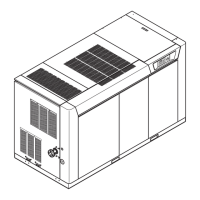
Cabinet
1. Remove access cover by loosening thumb screw and lifting cover
out.
Dust
Filters
2. Dust may be removed from filters with a stiff brush or a vacuum
cleaner. Filters may be washed with a mild detergent if necessary.
Allow to dry thoroughly before installing.
6.7.2
Inlet Air
1. Inspect the air filter element every month, Replace if dirty, if
service alert is present, or once per year.
Filter
2. To access air filter, remove left front access panel and remove the
four thumb screws from the filter mounting plate.
3. Install a new filter gasket with the filter.
6.7.3
Lube Oil
1. Remove and replace element when indicated by service alert or
once per year.
Filter
2. Install a new filter gasket with the filter.
6.7.4
Sump
1. Inspect element monthly, replace if element is saturated and oil is
present outside of the breather housing.
Breather
2. Replace element once per year.
 Loading...