KIMA00H1 (0204)
31
5.2.5
PLC
Analog
Inputs
(Figure 29)
The analog input modules have one LED for status indication. The
LED is labeled “OK” and is used to verify that there is no problem with
the analog module. If the OK LED is not on check the power supplies
and module connections. Cycle power to the PLC to “reboot”. If the OK
light is still off, replace the module.
5.2.6
Expansion
Module
Replacement
To replace an expansion module turn off power to the PLC. Remove
the wiring terminal by removing the terminal mounting screws (figure
29B). Push the module connector lever fully to the right for the module
being removed, as well as the lever on the module to the immediate
right of the module being removed. This disconnects internal electrical
connectors. Slide the bottom mount clip down and the top mount clip
up. Pull the module straight out.
Installation is in reverse order of the removal.
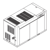
5.3
Motor
Starters
(Figure 31)
Kobelco KNW Series compressors are available with or without a
main motor starter. A mounted X-Line starter is standard. Optional
reduced voltage starters are shipped loose for separate mounting.
Several types and all makes of starters are available, including:
a. X-Line starter (Standard)
b. Solid State reduced voltage starter, with or without a bypass
contactor.
c. Wye-Delta reduced voltage starter, open or closed transition.
d. Auto-Transformer reduced voltage starter.
e. Part-Winding reduced voltage starter.
Note: May require special motor.
Accessories are available with the main motor starter, including circuit
breaker, fusible disconnect, non-fusible disconnect, power-factor
correction capacitors, phase monitor, or KW monitor. Consult the
factory and/or starter nameplate data for service and parts
information.
X-line starters are provided for starting the lube oil pump and the
cooling fan. The starters have integral Motor/Starter protectors (MSP)
which provide both short-circuit and overload protection. The
adjustable settings are to be set at the nameplate amperage of the
motor. The MSP’s have rotary operators with positions for off, on, and
tripped, and a manual test button. If the MSP trips turn the rotary
operator to the off position to reset, then turn back to on, before
attempting to reset the control panel alarm.
 Loading...