KIMA00H1 (0204)
3
1.2
Compressed
Air Flow
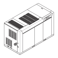
(Figure 2)
Air to be compressed undergoes two stages of filtration before being
compressed. The air enters the cabinet through an opening that is
equipped with a dust filter. The air then passes through the air inlet
silencer, a duct that is lined with a sound absorbing material. Then
the air is drawn through a high efficiency air filter. Filtered air flows
through a flex connector, into the capacity control valve, and then into
the inlet of the compressor first stage.
The compressor first stage compresses the filtered air to
approximately 37 PSIG. The compressed air is discharged into the air-
cooled intercooler where it is cooled to approximately 115°F (46°C).
The cooled, compressed air then passes through the moisture
separator to remove any condensed moisture from the air stream
before entering the compressor second stage.
The compressor second stage compresses interstage air to the
system operating pressure as controlled by the pressure setting. The
hot compressed air then passes through the system check valve and
air-cooled aftercooler where it is cooled to within approximately 15°F
(8°C) of the ambient air temperature. An ASME safety valve is
downstream of the check valve. The compressed air exits the unit
into a moisture separator, where condensed moisture is removed
before the air enters the plant air system.
The compressed air circuit is monitored with the following discrete
devices:
a. Inlet air filter service switch
b. Discharge high air pressure switch
c. Discharge air safety relief valve
The Programmable Logic Controller, PLC, (ref. Section 5.2) monitors
the compressed air circuit for the following:
a. First stage discharge air temperature
b. Interstage air pressure
c. Second stage suction air temperature
d. Second stage discharge air temperature
e. Compressor discharge air pressure
f. Compressor discharge air temperature
The air temperatures are displayed on the GT Terminal. The PLC
continuously monitors for excessive heat, providing a warning if
temperatures approach the recommended maximum and a shutdown
if they reach the limit. The interstage pressure is monitored to provide
load/unload indication and to confirm capacity control valve operation.
The pressure at the compressor discharge is monitored to provide
load and unload pressure control and a high pressure alarm.
 Loading...