KIMA00H1 (0204)
13
2. INSTALLATION
2.1
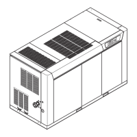
Inspection
(Figure 13)
The unit should be inspected for damage immediately upon receipt
from the carrier and any claims should be made to the delivery carrier
immediately.
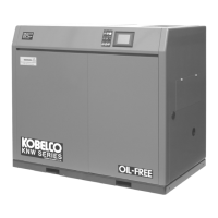
2.2
Handling
(Figures
14 & 15)
The compressor unit is equipped with forklift slots for ease in handling.
Spacer blocks should be placed between the compressor and forklift
mast to insure the cabinet will not be damaged during handling.
When handling the unit with an overhead crane, the lifting straps or
chains should pass through the forklift slots. Spacers and spreader
bars should be utilized to avoid damage to the enclosure.
2.3
Foundation
The compressor and motor assembly are vibration isolated from the
housing and base plate, additional isolation is not required. The
assembly should be mounted on a level, horizontal floor. Holes are
provided on each end of the compressor for installing bolt down
brackets.
2.4
Location
The unit should be installed indoors in a clean, well ventilated area,
free from excessive dust or dripping liquids. Do not install in an area
where chlorine gas, hydrogen sulfide gas, sulfur dioxide gas, highly
concentrated ozone, or any other toxic, corrosive or flammable gasses
are present.
WARNING:
The compressor shall not be located where potentially
explosive atmospheres may occur. The compressor and controls are
not rated for installation in hazardous (classified) locations.
Any contaminates in the atmosphere will be compressed along with
the air, therefore, it is important to provide a source of clean intake air.
An external source of clean inlet air to the compressor may need to be
provided.
The machine must be protected against freezing and excessive
ambient temperatures.
For ease of panel removal and maintenance provide ample clearance
around the compressor. A minimum of four feet is required in front of
the compressor. At least three feet is recommended for each end and
for the back.
2.5
Cooling
Air
(Figure 17)
The compressor should be located where sufficient ventilation is
available to cool the compressor. The cooling air inlet and discharge
must not be blocked. The warm air exiting the cooling air outlet must
be prevented from being drawn into the cooling air inlet. Ventilation
may need to be provided if the room in which the compressor is
installed exceeds 104°F (40°C) during compressor operation.
Air ducts may be connected to air inlets or outlets if desired. However
ducts must be sized to permit no more than 1” H
2
O restriction at full
flow.
 Loading...