7
2
2
4
4
4
4
4
4
2 2 2
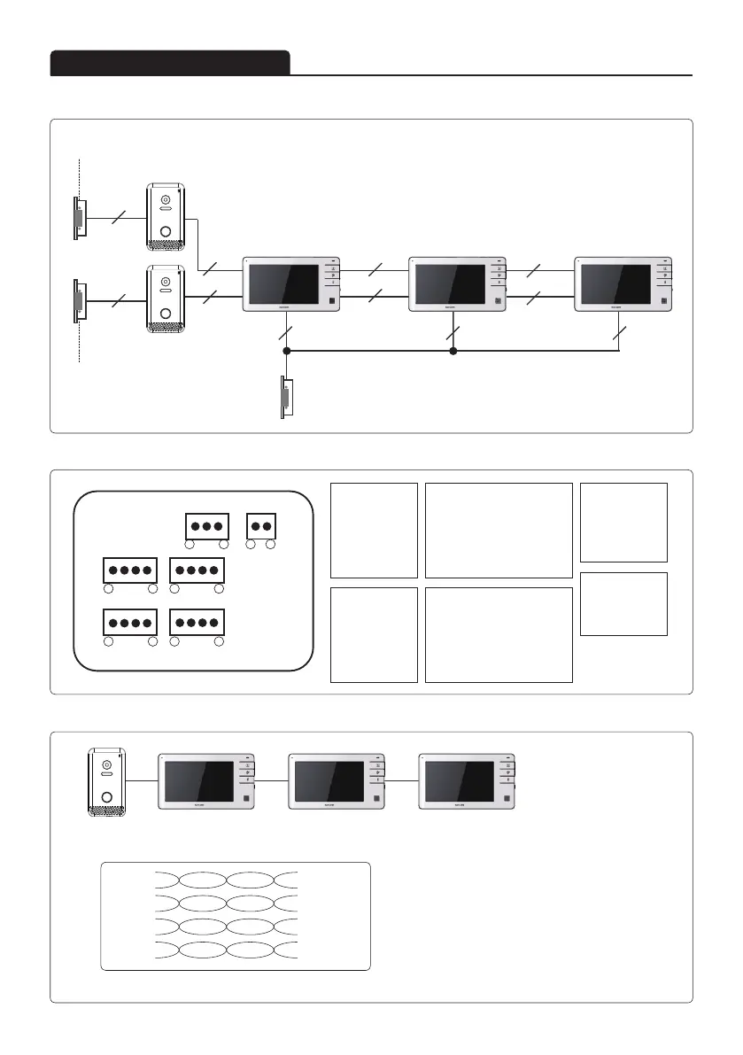
Product connection diagram
■ System configurations
Door opener(DC)
External power input
Door opener(DC)
External power input
Door opener(DC)
External power input
Monitor 1 Monitor 2 Monitor 3
Door camera 1
Door camera 2
A. CAMERA 1
① VCC
② GND
③ AUDIO
④ VIDEO
E. Door open
① COM
② NO
③ NC
C. CAMERA 1 for EX-monitor
① VCC
② GND
③ AUDIO
④ VIDEO
B. CAMERA 2
① VCC
② GND
③ AUDIO
④ VIDEO
a
※ When UTP CAT.5 wiring is used as in the following picture,
the total length of wiring (a,b,c) between camera and monitors is limited to 150m.
※ Slight reduction in image quality may be noticed depending on conditions of installation environment.
b c
F. DC Adaptor
① 12V
② GND
D. CAMERA 2 for EX-monitor
① VCC
② GND
③ AUDIO
④ VIDEO
■ Terminal
■ Cable requirement - Based on distance from camera to monitor
A B
C D
E F
1 2 1
1
1
1
1
3
4
4
4
4
Orange
W/Orange
① VCC
1 line (2 wire)
③ Audio
1 line (2 wire)
② GND
1 line (2 wire)
④ Video
1 line (2 wire)
Green
W/Green
Blue
W/Blue
Brown
W/Brown