EasyManuals Logo

Kodak Carousel 4200 User Manual

Kodak Carousel 4200
51 pages
To Next Page IconTo Next Page
To Previous Page IconTo Previous Page
Page #6 background imageLoading...
Page #6 background image
SERVICE MANUAL
6 18NOV97 – SM5440-1
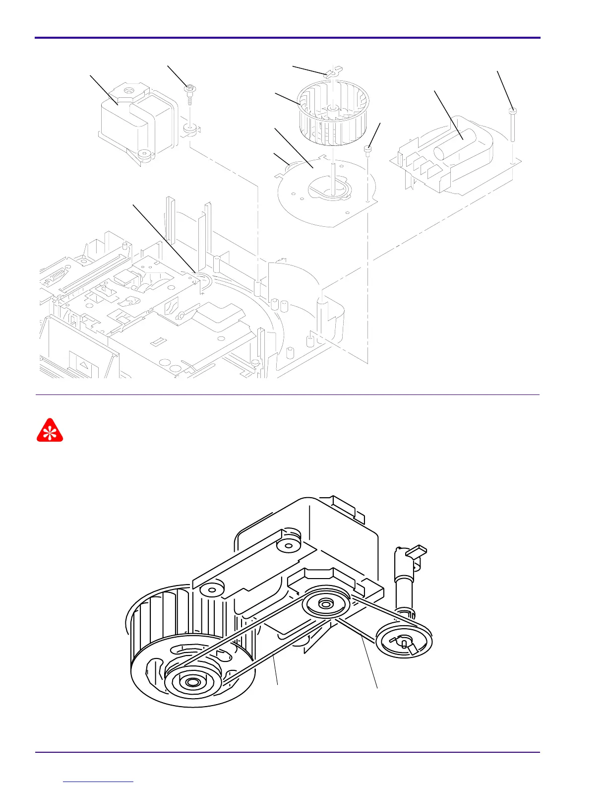
[19] Lift and remove the FAN SHAFT ASSEMBLY.
Installing the FAN SHAFT ASSEMBLY
Important
When installing the FAN and MECHANISM BELTS, install the MECHANISM BELT on the small MOTOR PULLEY,
and the FAN BELT on the large MOTOR PULLEY.
[1] Do the removal procedure for the FAN BELT and SHAFT in reverse order.
A100_0014HA
MECHANISM BELT
SCREW (2)
ASS4EMBLY
FAN PLATE
BLOWER ASSEMBLY
SCREW (3)
FAN BELT
FAN
RETAINER CLIP
MOTOR
SCREW
A100_0014HCA
A091_4015BA
A091_4015BCA
MECHANISM BELT
FAN BELT

Table of Contents

Other manuals for Kodak Carousel 4200

Questions and Answers:

Question and Answer IconNeed help?

Do you have a question about the Kodak Carousel 4200 and is the answer not in the manual?

Kodak Carousel 4200 Specifications

General IconGeneral
BrandKodak
ModelCarousel 4200
CategoryProjector
LanguageEnglish

Related product manuals