MDC-5200/5500 Series A table of content
0092655002-03 iii
3.1.3 Installation of the connecting cable 242J159098x-xxM ..................................................... 3-5
3.1.3.1 Scanner unit 4kW (RB806: MDC-5204/5504) ............................................................... 3-5
3.1.4 Installation of the connecting cable CW-845-xxM ............................................................. 3-6
3.1.4.1 Scanner unit 6kW (RB807: MDC-5206/5506) ............................................................... 3-6
3.1.4.2 Scanner unit 12kW (RB808: MDC-5212/5512) ........................................................... 3-11
3.1.4.3 Scanner unit 25kW (RB809: MDC-5225/5525) ........................................................... 3-18
3.2 Interconnection diagram of cable .......................................................................................... 3-23
3.2.1 242J159098 (MDC-5204/5504) ....................................................................................... 3-24
3.2.2 CW-845 (MDC-5206/5212/5225/5506/5512/5525) ......................................................... 3-25
3.3 Installation of the display unit ................................................................................................ 3-26
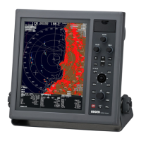
3.3.1 Installation of MRD-111 (MDC-5200 series) ................................................................... 3-28
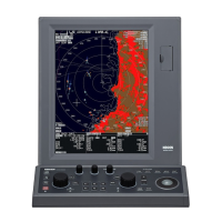
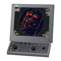
3.3.2 Installation of MRD-109/MRO-108 (MDC-5500 series) ................................................... 3-31
3.3.2.1 Table mounting of MRD-109 ....................................................................................... 3-31
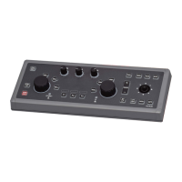
3.3.2.2 Table mounting of MRO-108 ....................................................................................... 3-32
3.3.2.3 Flush Mounting of MRD-109 ....................................................................................... 3-34
3.4 Cable connection to a Display unit ....................................................................................... 3-36
3.4.1 Cable connection for MRD-111 (MDC-5200 series) ....................................................... 3-37
3.4.2 Cable connection for MRD-109 (MDC-5500 series) ....................................................... 3-38
3.4.3 KODEN GPS compass connection ................................................................................. 3-39
3.4.4 Connecting a Gyro converter unit or THD ....................................................................... 3-40
3.4.5 Connecting a Position, Speed or other device of NMEA in/out ....................................... 3-41
3.4.6 Connecting an External monitor & external buzzer ......................................................... 3-42
3.4.7 AIS cable connection ....................................................................................................... 3-43
3.4.8 Cable connection for inter-switch .................................................................................... 3-44
3.4.8.1 Cable connection instructions for cross-over, dual and independent connection ....... 3-44
3.4.8.2 Cable connection for slave display used as a monitor ................................................ 3-45
Chapter 4 Setup after installation .............................................................................4-1
4.1 STARTUP menu ..................................................................................................................... 4-2
4.1.1 Tune adjustment (TUNE) ................................................................................................... 4-2
4.1.2 Heading adjustment (HL OFFSET) ................................................................................... 4-3
4.1.3 Transmitting delay time adjustment (TX DELAY) .............................................................. 4-4
4.1.4 Antenna height (ANT HEIGHT) ......................................................................................... 4-4
4.1.5 Antenna cable length (ANT CABLE) ................................................................................. 4-5
4.1.6 Main Bang Suppression (MBS) ......................................................................................... 4-5
4.1.7 Setup SEA curve (STC CURVE) ....................................................................................... 4-6
4.1.8 Function key usage ........................................................................................................... 4-7
4.1.9 RANGE ENABLE ............................................................................................................... 4-8
4.1.10 TIMES ENABLE ............................................................................................................ 4-11
4.1.11 LOGO ............................................................................................................................ 4-12