TP-6515 1/1112 Section 1 Specifications
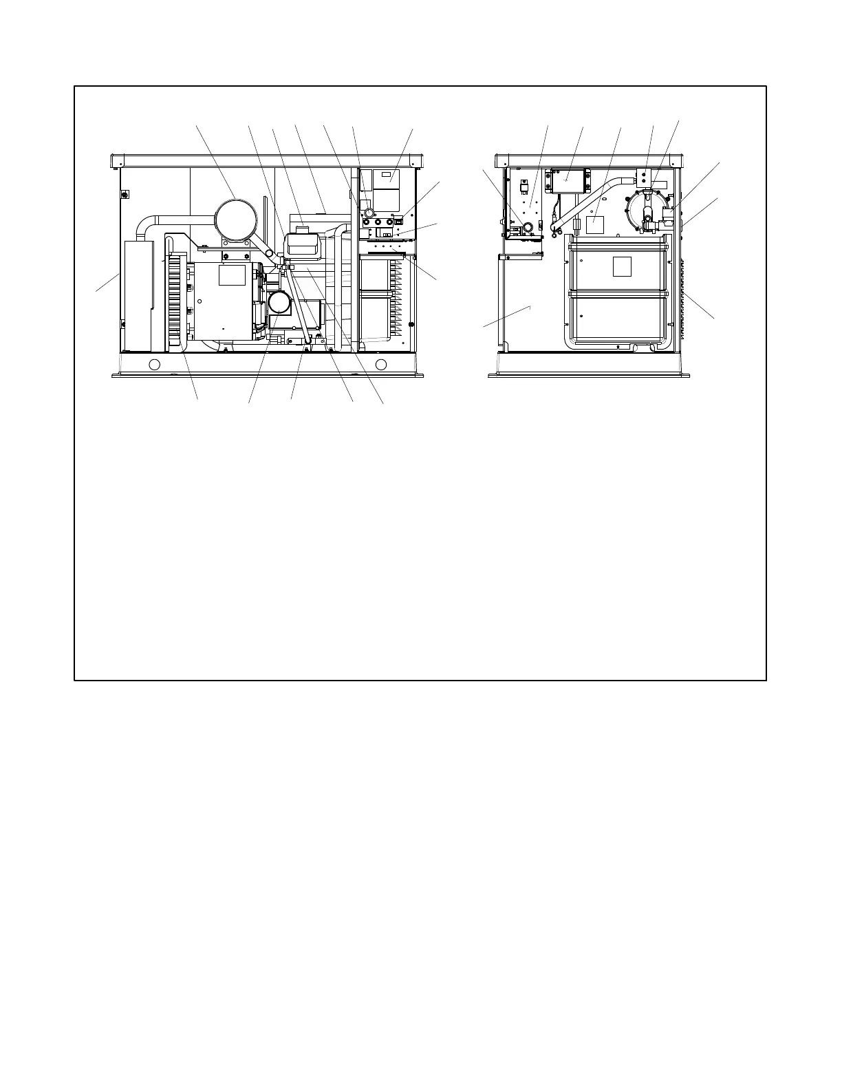
1.5 Service Views for Maintenance
ADV-7466-
1. Muffler
2. Oil check
3. Oil fill
4. Air cleaner
5. Fuses
6. RS-232 connector (for application program updates)
7. Controller user interface (see Figure 2-1)
8. Generator set master switch (RUN-OFF/RESET-AUTO)
9. Line circuit breaker (single-phase models)*
10. Field-connection terminal block location (single-phase
models)*
11. Spark plug l ocations (both sides)
12. Oil drain hose
13. Oil drain valve
14. Oil filter
15. Exhaust
16. Equipment ground
17. Relay board location (optional)
18. Battery charger (single-phase models)[
19. DSAI lead location (12 kW models)
20. Fuel block
21. Gas regulator assembly
22. Fuel solenoid valve
23. Fuel inlet
24. Air intake
25. Engine starting battery location (battery purchased separately)
1234
14 13
25
9
8
16
18 21
22
23
24
15
11
10
19 2017
12
5 6 7
24
* S ee Figure 1-3 for additional components for 3-phase models.
[ See Figure 2-9 for 3-phase battery charger locations.
Figure 1-1 Generator Set C omponents, 8.5/12 kW

 Loading...


