TP-6514 9/0932 Section 1 Installation
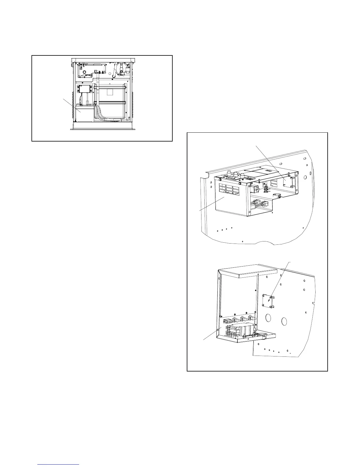
Figure 1-33 shows the location of the engine starting
battery. Standard battery cables provide easy
connection to the battery. Use the following procedure
to install and connect the battery.
ADV-7341A-B
1. Engine starting battery location
1
Figure 1-33 Battery Location, Air Intake End
Battery Installation Procedure
1. Ensure that the starting battery is fully charged
before placing the battery in service.
2. Clean the battery posts and/or adapters if
necessary.
3. Install the battery post adapters, if needed.
4. Place the battery in the housing.
5. Verify that the controller master switch is in the OFF
position.
6. Connect the positive (+) lead to the engine starting
battery.
7. Connect the negative (--) lead to the engine starting
battery.
Refer to the generator set operation manual and the
battery manufacturer’s instructions for battery
maintenance instructions.
1.10 Accessories
Have accessories installed by an authorized distributor/
dealer or a licensed electrician. Follow the installation
instructions provided with each kit. Use separate conduit
for AC and DC leads to reduce the possibility of electrical
interference. Verify that the leads and conduit do not
interfere with the operation of the generator set or
obstruct the service areas. Verify that the electrical
installation complies with the National Electrical Code
(NEC) and all applicable local codes. See Section 2,
Wiring Diagrams, for more information regarding
generator set electrical connections.
If there are no accessories, proceed to Section 1.11,
Prestart Installation Check.
1.10.1 Common Fault and Auxiliary Run
Relay Board
The optional relay board provides two additional relays
to control customer-provided equipment:
D Common fault relay, energized on a fault.
D Auxiliary run relay, energized when the generator set
is running.
See Figure 1-34 for the relay board location.
1. Relay board 2. Controller junction box
1
GM53102
2
1
8.5/12 kW
17/18 kW
2
Figure 1-34 Optional Relay Board Location

 Loading...


