TP-6196 10/09 107Section 7 Disassembly/Reassembly
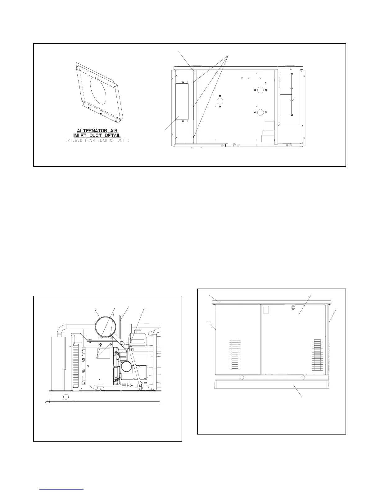
7. Reinstall the alternator air inlet duct. Orient the
duct as shown in Figure 7-18.
8. Install the exhaust shield. See Figure 7-18.
1
GM29253C-U
1. Alternator air inlet duct 2. Mounting screws (3 ea.) 3. Exhaust shield
3
2
Figure 7-18 Alternator Air Inlet Duct
9. Install the exhaust system. See Figure 7-19.
a. Install the heat shield onto the alternator
exhaust support using M8 hardware.
b. Using new gaskets, connect the engine
exhaust muffler to the engine at the flanges. Do
not final tighten the mounting hardware.
c. Secure the muffler mounting tab to the heat
shield with M8 hardware.
d. Torque the nuts securing the engine muffler
flange to the engine to 24 Nm (216 in. lb.).
ADV-7466
1
1. Engine exhaust muffler
2. Muffler bolts
3. Heat shield
4. Flange connection
5. Heat shield bolts
4
3
2
5
Figure 7-19 Exhaust System
10. Reconnect the alternator leads inside the controller
box. See the wiring diagrams in S ection 8 for
connections.
11. Reinstall the enclosure panels in reverse order of
removal. See Figure 7-20 and refer to Step 1 of the
disassembly instructions.
a. Install the non-service side housing panel.
b. Install the alternator end housing panel.
c. Install the generator set housing roof.
tp6196
2
1. Roof
2. Service-side door
3. Front panel (air intake end)
4. Mounting pad
5. Rear panel (alternator end)
5
1
3
4
Figure 7-20 Generator Set Enclosure

 Loading...


