TP-6196 10/0980 Section 6 Component Testing and Adjustment
1
GM57149
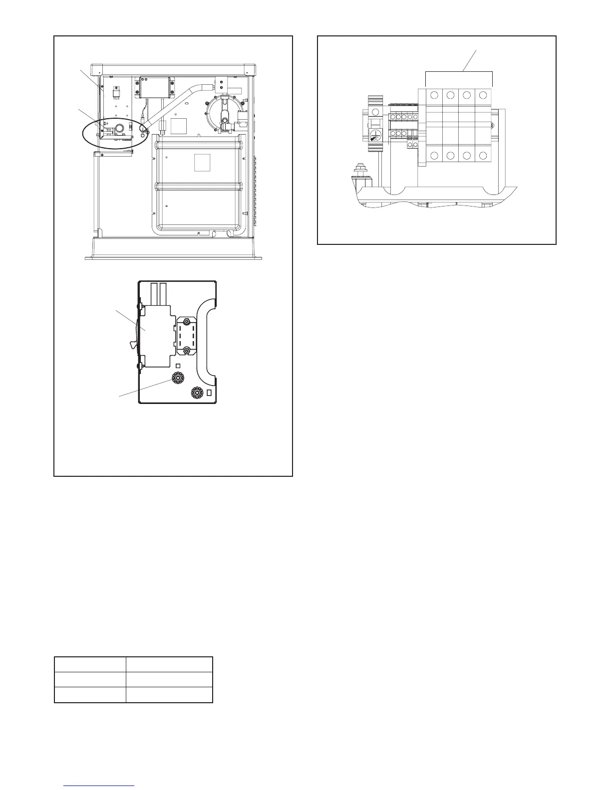
1. Controller box location
2. Line circuit breaker
3. Load connection terminal L0
Controller Box Detail
3
2
2
See
Detail
Figure 6-12 Circuit Breaker and L0 Terminal Location
4. Follow the controller instructions to step to the
voltage gain adjustment menu. Adjust the voltage
gain (parameter 2P) until the light flicker minimizes.
Save the settings.
5. Check and readjust the voltage if necessary.
6. Set the voltmeter to measure frequency. Adjust the
engine speed to the cut-in frequency shown in
Figure 6-13 by adjusting the engine governor
speed (parameter 4P) through the ADC controller.
See Section 4.5.
Frequency
Cut-In Frequency
60 Hz 57.5 Hz
50 Hz 47.5 Hz
Figure 6-13 Cut-In Frequencies
GM66010
L0 L1 L2 L3
1
1. Measure voltage across circuit breaker terminals L0 and L1,
L2, or L3
Figure 6-14 Voltage Measurement, Three-Phase
Models
7. Set the voltmeter to measure voltage. Adjust the
volts/Hz (parameter 3P) until the voltage level
measured by the voltmeter begins to drop. When
set, the generator (as load is applied) attempts to
maintain normal output until the engine speed
drops below the cut-in frequency set in step 6.
Note: See Section 6.7.3 for more information on
the volts/Hz (droop) adjustment.
8. Set the voltmeter to measure frequency. Adjust the
engine speed to the operating frequency (50 or
60 Hz) by adjusting the engine governor speed
(parameter 4P) through the ADC controller.
9. Readjust the voltage gain (parameter 2P) until the
light flicker minimizes, if necessary.
10. Check the voltage. Readjust the voltage
(parameter 1P), if necessary.
11. Save the settings as instructed in Section 4.5.
Note: The controller will revert to the previous
settings at the next startup if the changes are
not saved.
12. Stop the generator set.

 Loading...


