TP-6196 10/09 97Section 6 Component Testing and Adjustment
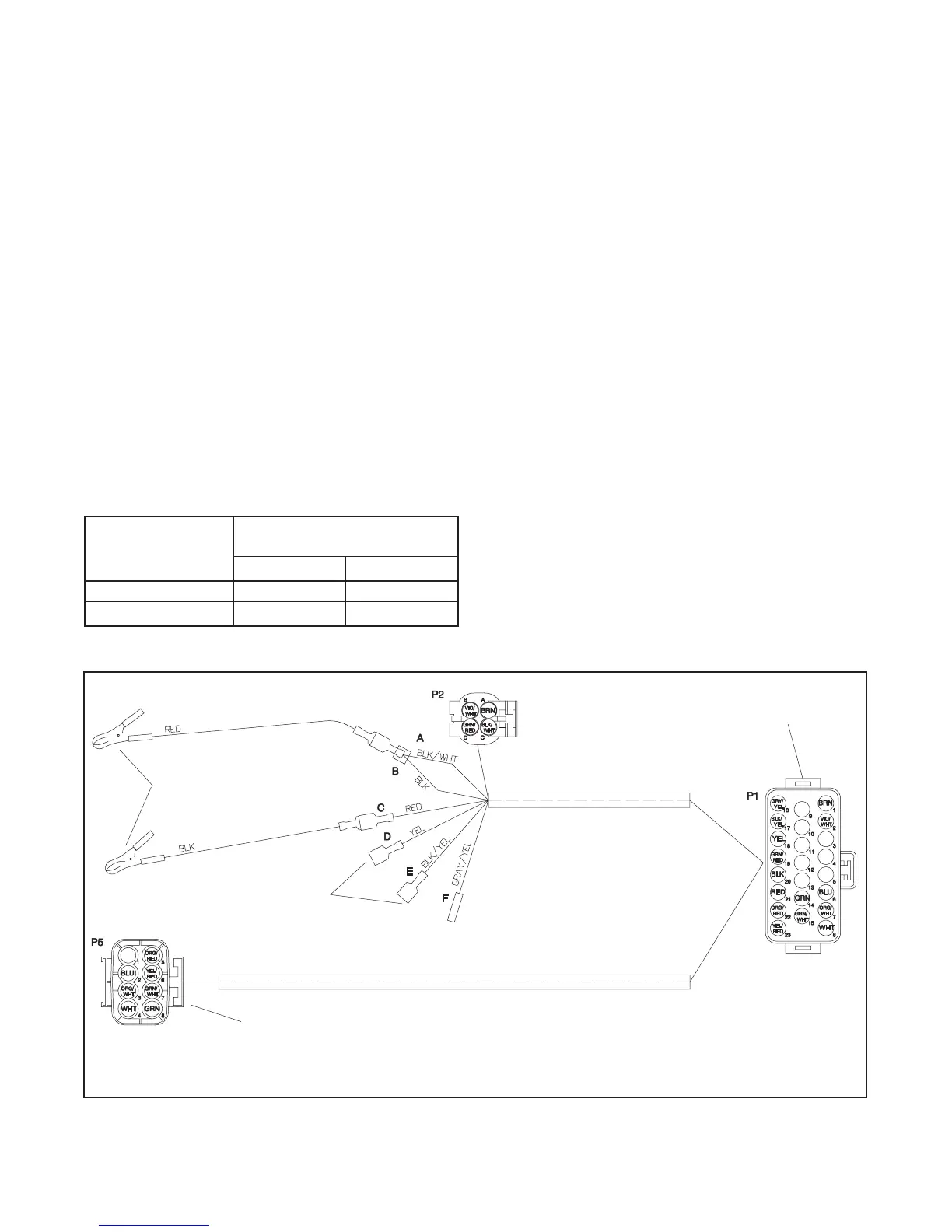
4. Connect the oxygen sensor to the engine starting
battery, control module, and voltmeter as shown in
Figure 6-40.
5. Reconnect power to the battery charger.
6. Place the controller master switch in the RUN
position to start the generator set.
7. Allow the generator set to run until the engine
reaches normal operating temperature.
8. With the generator set at normal operating
temperature, apply rated load.
9. Connect one of the DVM leads to the oxygen
sensor lead. Connect the other DVM lead to
ground and measure the output voltage of the
oxygen sensor (potential to ground).
10. Adjust the fuel metering valve as required to obtain
the output from the oxygen sensor specified in
Figure 6-39. The output of the oxygen sensor
reads high when the mixture is fuel-rich and close
to zero volts when the mixture is lean.
Model
Oxygen Sensor Reading,
VDC
Natural Gas LP
8.5kW 2.40±0.05 2.25±0.05
12kW
2.60±0.05 2.60±0.05
Figure 6-39 Acceptable Oxygen Sensor Readings
11. When the fuel mixture is correct, use thread sealant
to seal the metering valve adjustment screws.
12. Remove the load and allow the generator set to run
unloaded to cool for at least 5–10 minutes.
13. Place the generator set master switch in the OFF
position.
14. Disconnect the generator set engine starting
battery, negative (--) lead first.
15. Allow the generator set exhaust system to cool.
16. Disconnect the DVM leads from the oxygen
sensor.
17. Remove the oxygen sensor from exhaust manifold.
18. Apply a small amount of antiseize compound to
exhaust plug and reinstall the plug into the exhaust
manifold.
19. Check that the generator set master switch is in the
OFF position.
20. Reconnect the generator set engine starting
battery, negative (--) lead last.
21. Reconnect power to the battery charger.
1. Battery power supply connection
2. Digital voltmeter (DVM) connection
3. Air/fuel control module connection
4. Oxygen sensor connection
GM-28981-
1
2
3
4
Figure 6-40 UEGO Sensor Interface Harness GM28981 Electrical Connections

 Loading...


