TP-6196 10/09 99Section 6 Component Testing and Adjustment
To further check generator set components, disconnect
the battery and remove wiring harness plugs from the
controller circuit board. Use an ohmmeter to check the
continuity of the components listed in Figure 6-45. Also
see Section 8, Wiring Diagrams.
Figure 6-45 gives resistance readings for functional
components. A zero reading on the ohmmeter indicates
continuity. No ohmmeter reading indicates very high
resistance or an open circuit. A measurement that
varies significantly from the value shown in the table
indicates a faulty component; replace faulty
components.
Note: Disconnect the generator set battery before
performing continuity checks to prevent damage
to the ohmmeter.
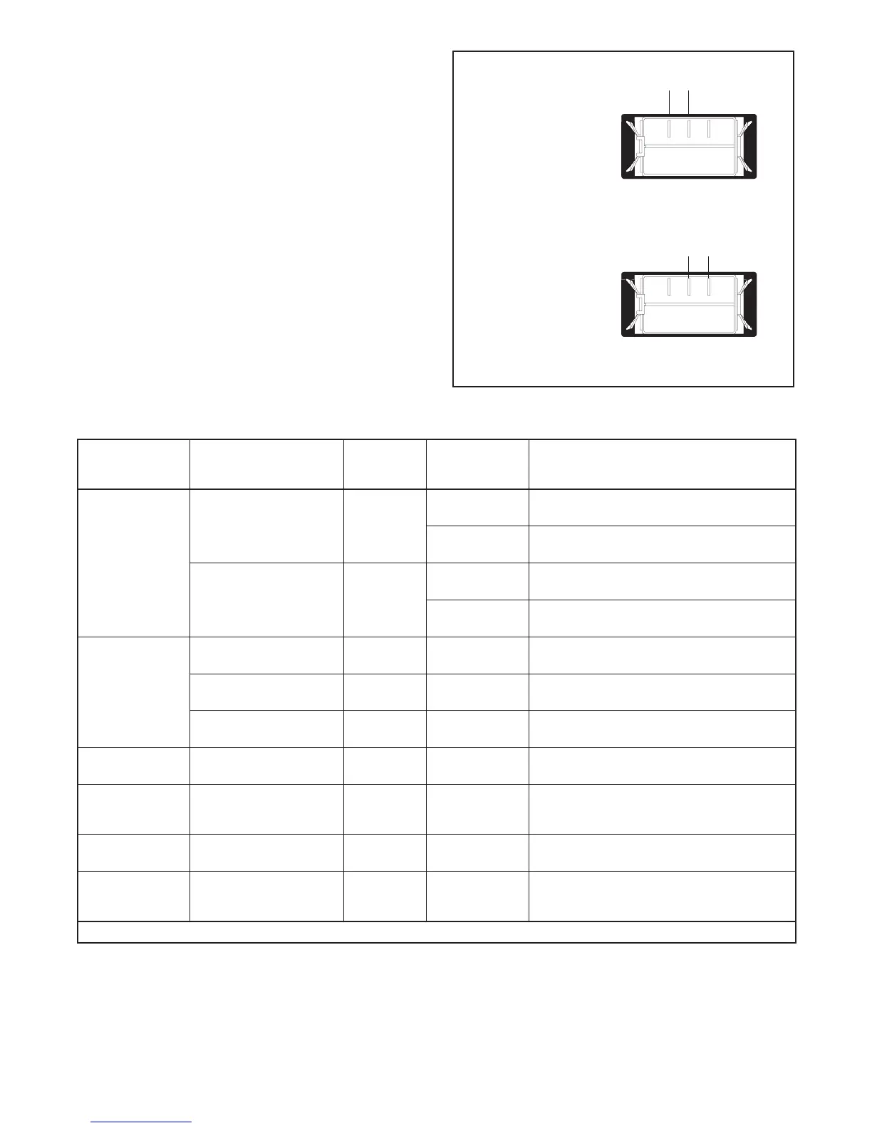
321
321
Master S witch in
RUN Posit ion
Master S witch in
AUTO Posi tion
Zero ohms (continuity) across
RUN and COM terminals
Zero ohms (continuity) across
COM and AUTO terminals
AUTO
RUN
VBAT
AUTO
RUN
VBAT
Figure 6-44 Generator Set Master Switch Continuity
Checks
Component
Ohmmeter
Connections
Ohmmeter
Scale
Generator Set
Master Switch
Position
Ohmmeter Readings for
Operative Components*
Generator set
master switch
RUN and VBAT (see
Figure 6-44)
R x 100
RUN Zero ohms (continuity). Any other reading
indicates a bad switch.
OFF/RESET No reading (open circuit). Any other reading
indicates a bad switch.
AUTO and VBAT
(see Figure 6-44)
R x 100
AUTO Zero ohms (continuity). Any other reading
indicates a bad switch.
OFF/RESET No reading (open circuit). Any other reading
indicates a bad switch.
P1 wi ring
harness
P1-27 and ground R x 1 OFF/RESET Zero ohms (continuity). Any other reading
indicates a poor ground connection.
P15-1 and P15-3
(stator leads 11 and 44)
R x 1 OFF/RESET Zero ohms (continuity). If no continuity,
check wiring.
P16-3 and P16-6 (stator
leads 55 and 66)
R x 1 OFF/RESET Zero ohms (continuity). If no continuity,
check fuse F1 and wiring.
Controller fuse
and wiring
P1-24 and battery
positive (+)
R x 100 OFF/RESET Zero ohms (continuity). If no continuity is
found, check fuse F3 and wiring.
Auxiliary winding
fuse 20 amp fuse
P16-3 and stator lead 55 R x 100 OFF/RESET Zero ohms (continuity). If no continuity is
found, check for an open circuit and/or a
blown fuse.
Low oil pressure
(LOP) switch *
Lead 13 and ground
(engine block)
R x 100 OFF/RESET Zero ohms (continuity). No continuity
indicates a bad switch and/or wiring.
Temperature
sensor (CTS) *
P1-8 and P1-9 R x 1000 OFF/RESET 180--2500 ohms, depending on engine
temperature. Zero ohms or an open circuit
indicates bad wiring or a bad switch.
* See Section 6.11.2, Fault Shutdown Switches
Figure 6-45 Continuity Checks
 Loading...


