2 TT-1619 7/15
KOHLER CO., Kohler, Wisconsin 53044 USA
Phone 920-457-4441, Fax 920-459-1646
For the nearest sales and service outlet in the
US and Canada, phone 1-800-544-2444
KOHLERPower.com
Kohler Power Systems
Asia Pacific Headquarters
7 Jurong Pier Road
Singapore 619159
Phone (65) 6264-6422, Fax (65) 6264-6455
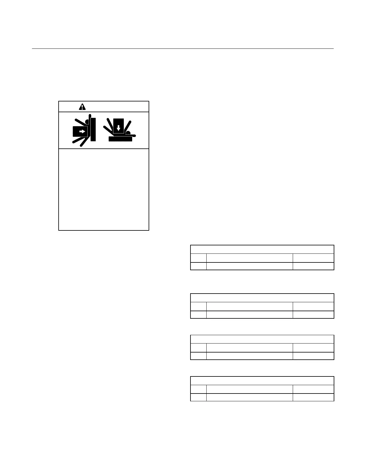
Safety Precautions
Observe the following safety precautions while installing
the mounting pad. Refer to the generator Installation
Manual for additional precautions and instructions.
Unbalanced and elevated weight.
Improper lifting can cause severe
injury or death and equipment
damage.
Do not lift the generator set from the
engine or alternator eyes. Never
stand under a unit being lifted.
Alwaysmaintainasafedistancefrom
the unit being lifted.
See the lifting instructions in the
installation manual that was provided
with the unit.
WARNING
Lifting the Pad
See the weight listed under Specifications. Use a cart,
dolly, or hoist to move the pad into place.
To lift with a hoist, install four 3/8--16 eyebolts
(installer-supplied) at least 25 mm (1 in.) into the
threaded inserts on the pad and use proper size rigging.
Do not attempt to lift the generator and mounting pad
together. Do not lift the pad higher than necessary to
move it into place. Do not stand under the pad when
lifting it.
Installation Procedure
Note: Refer to the generator Installation Manual for
important clearance information and location
requirements before installing the generator
mounting pad.
1. Select a level area to mount the generator set.
Compress the soil if it is loose.
2. Set the mounting pad in place. Position the curved
edge of the pad to align with the front of the
generator set and to face away from adjacent
buildings. Check that the pad is level and that the
generator service panels will be accessible.
3. Follow the precautions in the generator installation
manual when lifting the generator into place. Place
the generator set on the mounting pad with the
mounting holes aligned with the inserts on the pad.
Note: If necessary, use a 7/16 inch drill to carefully
enlarge the holes in the base of the
generator set. Use extreme care to avoid
damaging the base.
4. Use four 3/8--16 x 1 1/4 inch screws to secure the
generator to the mounting pad.
5. Refer to the generator Installation Manual for
further generator set installation instructions.
Parts List
Three-Inch Mounting Pad Kit, 14/20RESA(L) and
20RESC(L)
Kit: GM90969-KP1-QS
Qty. Description Part Number
10 Pad, Concrete Mounting, 3” GM90969
Four-Inch Mounting Pad Kit, 14/20RESA(L) and
20RESC(L)
Kit: GM90969-KP2-QS
Qty. Description Part Number
10 Pad, Concrete Mounting, 4” GM90970
Three-Inch Mounting Pad Kit, 8/10/12RESV(L)
Kit: GM92228-KP1-QS
Qty. Description Part Number
10 Pad, Concrete Mounting, 3” GM92226
Four-Inch Mounting Pad Kit, 8/10/12RESV(L)
Kit: GM92228-KP2-QS
Qty. Description Part Number
10 Pad, Concrete Mounting, 4” GM92227
vailability is subject to change without notice. Kohler Co. reserves the
right to change the design or specifications without notice and without any
obligation or liability whatsoever. Contact your local Kohlerr generator
set distributor for availability.
2014, 2015 by Kohler Co. All rights reserved.
 Loading...


