8-10 Disassembly/Reassembly TP-5606 6/02
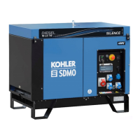
1
1. End Bracket
Figure 8-30. Removing the End Bracket
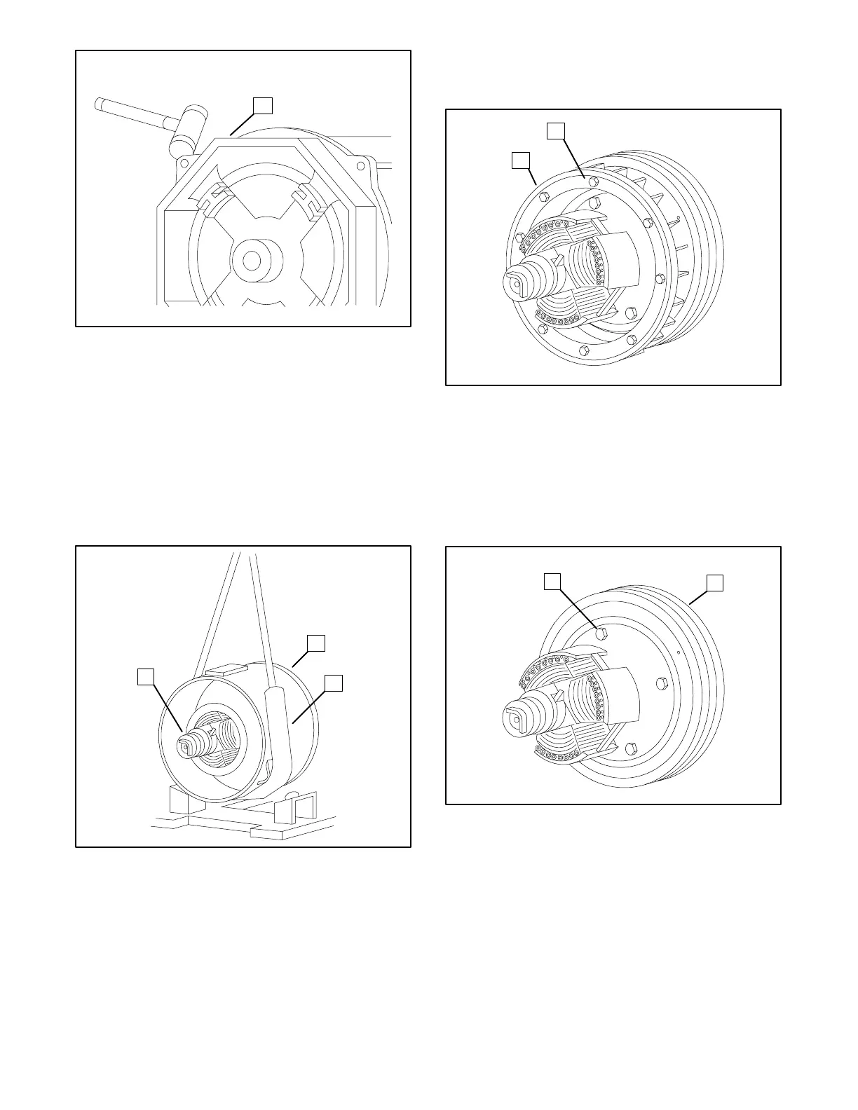
19. Carefully remove the stator by pulling the stator
over the rotor assembly. See Figure 8-31.
NOTE
Due to the heavy weight, it is recommended that
the stator be supported by a hoist during removal to
prevent damage to the stator, rotor, and/or
armature drive disks.
1. Stator
2. Sling
3. Rotor
1
2
3
Figure 8-31. Removing the Stator
20. Remove the eight screws and four spacers
securing the generator fan. Then carefully remove
the cooling fan. See Figure 8-32.
1. Fan 2. Screw
1
2
Figure 8-32. Removing the Generator Cooling Fan
21. Support the rotor assembly with a strap and hoist.
Remove the eight screws securing the armature
drive disks to the engine using a 13-mm socket
wrench and ratchet. Remove the rotor assembly
and place it on a bench. See Figure 8-33.
1. Screws 2. Rotor Assembly
1
2
Figure 8-33. Removing the Rotor Assembly
22. Remove the eight screws securing the armature
drive disks to the rotor assembly using a 9/16-inch
socket wrench and ratchet. See Figure 8-34.
 Loading...