136 TP-6694 6/22
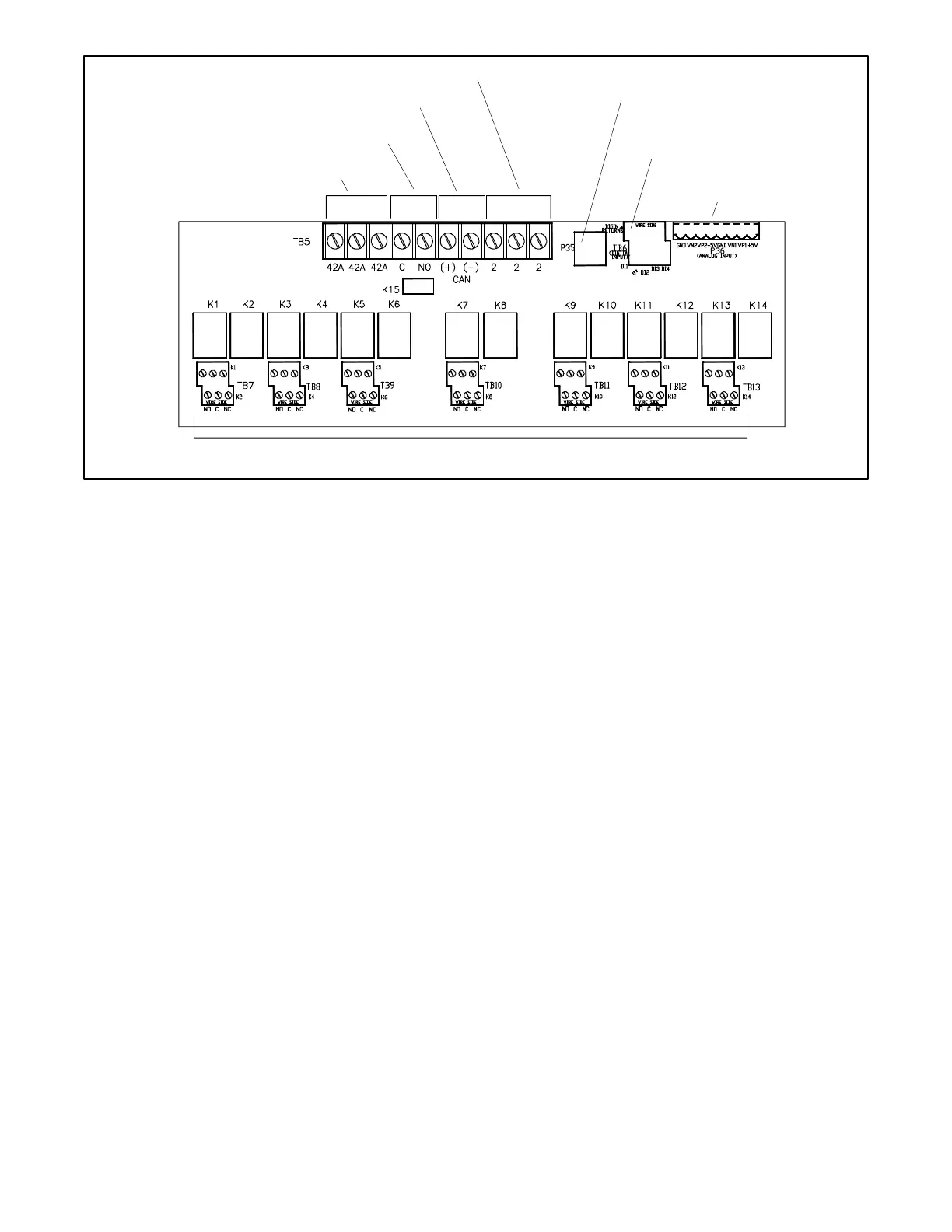
Figure 67 4-Input/15-Output Module Customer Connections
Connections
Leads 42A and 2 provide power to the relays. Do not use terminals 42A (+) or 2 (GND) on the controller connection kit terminal
strip to supply voltage to user-supplied accessories. User-supplied DC accessories require separate leads connected directly to
the battery for the voltage supply. Attach user-supplied 12/24-volt DC accessories to the battery positive (+) connection at the
starter solenoid and to the battery negative (-) connection at the engine ground. The 120 VAC accessories require a user-
supplied voltage source.
Note:
A maximum of three inputs may be connected to a single relay driver output. Inputs include dry contacts, remote annunciator,
common failure alarm, A/V alarm, and shunt trip line circuit breaker.
Note:
Only one 4-input/15-output module can be connected to the controller.
TB6 8-position terminal block,
digital inputs/digital returns
(D11, D12, D13 and D14)
TB7 through TB13, connections for relays K1 through K14 with
Normally Open (NO) and Normally Closed (NC) contacts
 Loading...