TP-6862 6/1416 Section 3 Cooling System
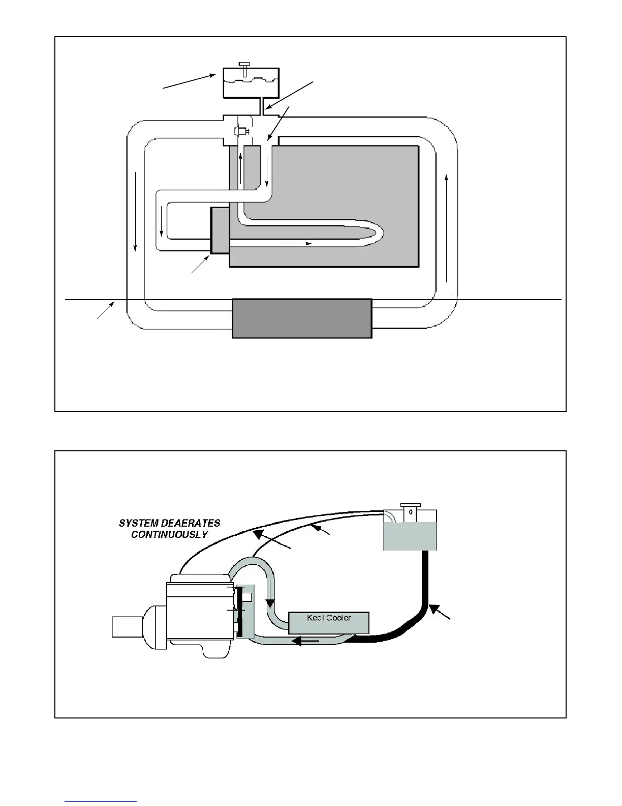
* If a single fill/vent line between the expansion tank and the engine cannot be used, separate lines must be used for filling and venting the
tank. A 1/4 in. (6 mm) vent line is routed from the engine top tank to the expansion tank. The expansion tank fill line goes from the bottom of
the expansion tank to the top of the keel cooler return line. A separate line, dedicated to filling the system, must be sized to meet the fill rate
requirements published by the engine manufacturer.
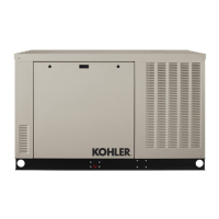
Overflow bottle or
tank with cap
Keel Cooler
Hull
1 1/4 in. (31.75 mm) ID fill/vent line with
a slope not less than 30 degrees *
Bypass
Water pump
Return LineOutlet Line
Inlet Line
Engine Block &
Exhaust Manifold
Figure 3-7 Keel Cooling System Installation (Single Fill/Vent Line)
3/4” min. fill line
to water pump inlet.
(Tee in as close to the engine
pump inlet as practical in
customer-supplied piping).
1/4” max. vent lines
from high points in
system to top of tank.
Figure 3-8 Keel Cooling System Installation (Multiple Vent Lines)
 Loading...