TP-6774 2/14a 43Section 7 Controller
Section 7 Controller
7.1 Introduction
This section covers operation, configuration,
adjustment, and replacement of the ADC IId controller.
See Section 6 for troubleshooting procedures.
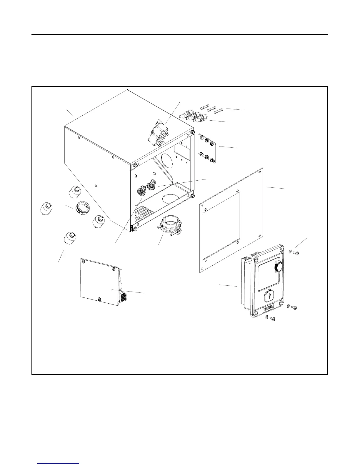
See Figure 7-1 for the locations of the controller and
related components.
1
GM76137
1. Junction box
2. Preheat relays (qty. 2) located inside junction box
3. F1, F2, and F3 fuses (qty. 3)
4. Fuse holders (qty. 3)
5. Line circuit breaker cover plate
6. GRD lead connection
7. LO lead connection
8. Cable connector
9. Bushing
10. Vibromounts (qty. 4)
11. Junction box controller panel
12. Screws and washers (qty. 4)
13. Advanced Digital Control IId
14. Battery charging module (shown removed from inside of the
junction box)
6
7
10
2
5
4
3
9
8
11
12
13
14
Figure 7-1 Advanced Digital Control IId (ADC IId) and Junction Box Detail
 Loading...


