TP-6774 2/14a98 Section 9 Generator Disassembly/Reassembly
9.2 Collector Ring and Bearing
Replacement (6EKOD/5EFKOD
Model)
1. Unsolder the collector ring leads from the collector
ring terminals.
2. Remove the collector rings with a three-jaw puller.
3. Remove the bearing with a three-jaw puller.
4. Press the new bearing onto the rotor shaft.
5. Align the collector ring keyway with the keyway on
the rotor shaft. See Figure 9-14.
6. Press the new collector rings onto the rotor shaft.
Note: The new collector rings must be turned down to a
finish of 32 micro inches using a lathe and
commutator stones. Turn down the collector
rings on the rotor shaft.
7. Solder the leads onto the collector ring terminals.
Bend over terminal and insulate with heat shrink
tubing. Terminal and insulator not to extend more
than 6.4 mm (0.25 in.) beyond collector ring. See
Figure 9-14.
8. Test to ensure continuity at the collector rings.
Max. finish 32 micro inches
Max. eccentricity mm (in.) 0.08 (0.003)
Max. out-of-round mm (in.) 0.01 (0.0002)
Figure 9-13 Collector Ring Dimensions
1
GM71834-A
1. Collector ring
Figure 9-14 Rotor Assembly
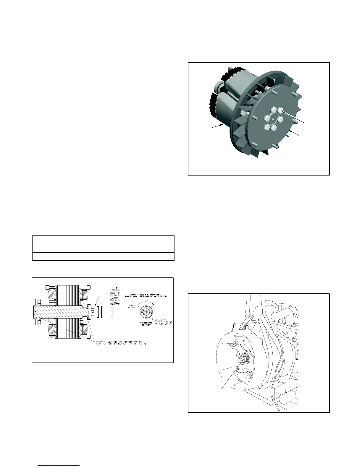
9.3 Reassembly
1. Clamp the rotor in a soft-jaw vise. Install a new
drive disc and fan on the rotor. Tighten the six bolts
to 45 Nm (34 ft. lbs.) See Figure 9-15.
GM73473-A
3
1. Rotor
2. Drive disc
3. Bolt
1
2
Figure 9-15 Drive Disc Installation
2. Install the rotor/drive disc assembly on the engine
flywheel using six studs and nuts torqued to 23 Nm
(17 ft. lbs.).
3. Align the fan to the rotor/drive disc assembly using
the mark created in the disassembly procedure.
Note: Install the fan with the flange side facing
away from the flywheel.
4. Replace the O-ring in the end bracket bearing bore.
Use a sling to support the stator assembly while
installing the stator over the rotor. Do not damage
the rotor. See Figure 9-16.
5588612
1
1. O-ring
Figure 9-16 Stator Installation