TP-6049 9/02 21Section 5 Wiring Diagrams
Section 5 Wiring Diagrams
5.1 Specification Numbers
At the time of print, this manual applied to the model
numbers and specification (spec) numbers in
Figure 5-1. On occasion the manufacturer may provide
this manual with units that are not listed below, such as
when similar new specs are created prior to the updated
reprint or in other cases when the manual is a suitable
substitute for a manual under development.
Model No.
Spec. No.
Controller
Fault Lamp
8.5RMY PA-195021 No
8.5RMY PA-195025 Yes
8.5RMY GM16902-GA1 Ye s
8.5RMY GM24829-GA1 Ye s
11RMY PA-195022 No
11RMY PA-195026 Yes
11RMY GM16902-GA2 Yes
11RMY GM24829-GA2 Yes
Figure 5-1 Generator Set Specification Numbers
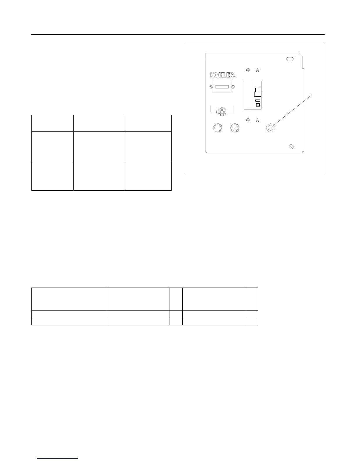
5.2 Controller Wiring Diagram
Reference
Compare the front of the generator set controller with
Figure 5-2. Use the version 1 diagrams for units that do
not have a fault lamp on the front of the controller. Use
the version 2 diagrams for units that have a fault lamp.
Figure 5-3 lists the wiring diagram numbers and
locations.
GM10615
1. Fault lamp (not included on early models)
1
AUTOOFF
RESET/
RUN
R
F2 10 AMP
TYPE ABCTYPE ABC
F1 10 AMP
50
ON
OFF
FAU LT
Figure 5-2 Controller
Wiring Diagram Description
Controllers
Without Fault Lamps
(Version 1)
Pg
Controllers
With Fault Lamps
(Version 2)
Pg
Schematic Diagram ADV-6297-D 23 ADV-6524- 25
Point-to-Point Wiring Diagram GM10164-A 24 GM10619- 26
Figure 5-3 Controller Wiring Diagrams
 Loading...