TP-6049 9/02 27Section 6 Installation
Section 6 Installation
6.1 General
Installation must comply with these installation
instructions. Install the generator set to comply with
state and local code requirements.
Use the specifications provided here only in the initial
planning. Use the respective spec sheets, dimension
drawings, and wiring diagrams for installation. Contact
an authorized service distributor/dealer for the most
current information.
Provide a 110- or 120-volt outlet connected to the utility
power supply for the carburetor heater and battery
charger, if used.
6.2 Air Requirements
The generator set requires correct air flow for cooling
and combustion. The inlet and outlet openings in the
sound enclosure housing provide the cooling and
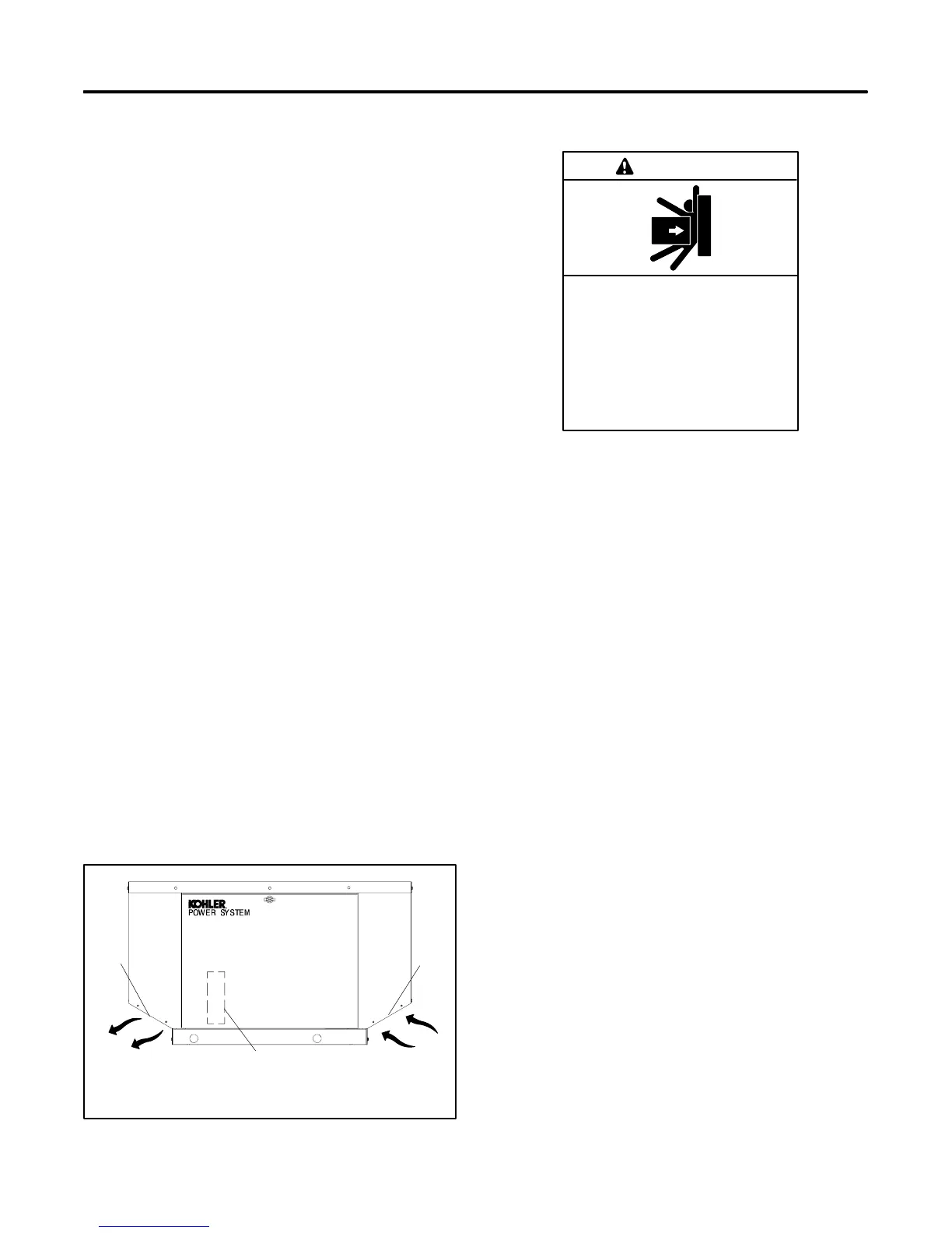
combustion air. Figure 6-1 shows the locations of the
cooling air intake and exhaust vents. Do not block or
otherwise interfere with the airflow through these
openings.
Inspect the air inlet and outlet openings inside and
outside the housing to ensure that debris does not block
the air flow. Mount the generator so that the hot exhaust
does not blow on plants or shrubs. Maintain a minimum
of 0.3 m (1 ft.) between the exhaust outlet and
combustible materials.
6.3 Exhaust Requirements
The exhaust system is complete for generator sets
installed outdoors. Do not install this generator set
indoors.
GM24829
2
1. Exhaust outlet
2. Alternator air intake (on back)
3. Engine air intake
3
1
Figure 6-1 Cooling Air Intake and Exhaust
6.4 Weight
Unbalanced weight.
Improper lifting can cause severe
injury or death and equipment
damage.
Do not use lifting eyes.
Lift the generator set using lifting bars
inserted through the lifting holes on
the skid.
WARNING
The genertor set weighs approximately 182 kg
(400 lbs.). Use lifting bars inserted through the holes in
the skid to lift the unit. See Figure 6-2 for lifting hole
locations.
6.5 Generator Set Inspection
Complete a thorough inspection of the generator set.
Check for the following:
1. Inspect the generator set for loose or damaged
parts or wires. Repair or tighten any loose parts
before installation.
2. Check the engine oil. Fill, if necessary, with the
recommended make and grade of oil. See
Section 3.3.3 for engine oil recommendations.
6.6 Mounting
Do not install the generator set directly on the ground.
Mount the generator set on a level pad. Use a simple
concrete slab, precast base, or other non-combustible,
stable material. The mounting pad should be at least
1320 mm (52 in.) long and 800 mm (31.6 in.) wide.
Center the unit on the mounting pad.
Figure 6-2 shows the generator set dimensions,
mounting hole locations, and fuel and electric stub-up
locations. The drawing dimensions are shown in mm
with inches in parentheses.
Secure the generator set and ensure that it does not
move while operating.
 Loading...