TP-6049 9/0232 Section 6 Installation
6.8.2 AC Load Lead Connections
Have an authorized distributor/dealer or a licensed
electrician make the following load connections.
Connect the AC output leads in the controller
compartment to the AC circuit breaker. Route AC and
DC leads through the bottom of the generator set or
through flexible conduit directly to the AC circuit breaker
box. See Figure 6-2. Verify that the leads and conduit
do not interfere with the operation of the generator set or
obstruct the service areas.
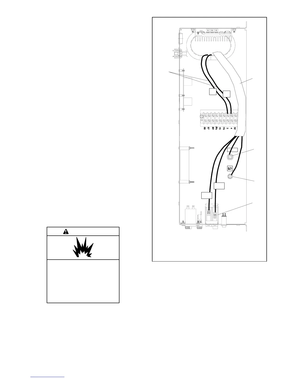
See Figure 6-8 and Section 5, Wiring Diagrams, for the
generator set electrical connections. Make the following
AC connections:
1. Connect the output leads going to the transfer
switch (L1/L2 black leads) to the AC circuit breaker
load side (top).
2. Connect the L0 white leads from the ATS and the
main panel to the neutral stud.
3. Connect the green lead to the equipment ground
stud (labeled GRD).
Verify that the electrical installation complies with the
National Electrical Code (NEC) and all applicable local
and state codes.
NOTICE
Canadian installations only. For standby service connect
the output of the generator set to a suitably rated transfer
switch in accordance with Canadian Electrical Code, Part 1.
6.8.3 Battery
Explosion.
Can cause severe injury or death.
Relays in the battery charger
cause arcs or sparks.
Locate the battery in a well-ventilated
area. Isolate the battery charger from
explosive fumes.
WARNING
GRD
6868
6767
FPFP
FNFN
7070
7N7N
33
44
3232
3
4
2
1
GM10615A-A
1. AC load leads
2. Ground terminal (GRD)
3. Neutral terminal (L0)
4. Circuit breaker
5. ATS engine start leads
5
L2
L1
3
4
Figure 6-8 Typical Controller, Top View with
Field-Installed Wiring
 Loading...