TP-5867 11/02 27Section 4 Controller Troubleshooting
Grounding electrical equipment. Hazardous voltage can
cause severe injury or death. Electrocution is possible
whenever electricity is present. Open the main circuit
breakers of all power sources before servicing the equipment.
Configure the installation to electrically ground the generator
set, transfer switch, and related equipment and electrical
circuits to comply with applicable codes and standards. Never
contact electrical leads or appliances when standing in water
or on wet ground because these conditions increase the risk of
electrocution.
Short circuits. Hazardous voltage/current can cause
severe injury or death. Short circuits can cause bodily injury
and/or equipment damage. Do not contact electrical
connections with tools or jewelry while making adjustments or
repairs. Remove all jewelry before servicing the equipment.
Some controller circuit board components can be tested
without removing the component from the board.
Perform these checks prior to installing a new board and
attempting start-up. Section 3, Troubleshooting, lists
most of the tests. Use a high-quality multimeter and
follow the manufacturer ’s instructions. To obtain
accurate readings when testing, remove all circuit board
connectors and conformal coating (transparent
insulation) from component terminals. Use Figure 4-9
and the controller circuit board illustration; see
Figure 4-6 or Figure 4-7.
The controller circuit board has light-emitting diodes
(LEDs) that indicate relay coil power and aid in circuit
board and generator fault detection. When the K1, K2,
K3, or K4 relays receive power, the corresponding LED
lights. The LED does not indicate whether the relay coil
is functioning. Determine if the relay coil is functioning
by analyzing generator faults by performing a continuity
test on the relay coil.
Overspeed Setting
A potentiometer on the relay controller circuit board
adjusts the overspeed setting. See Figure 4-6 or
Figure 4-7 and the table in Figure 4-8 to identify the
potentiometer used to adjust the overspeed setting.
When investigating a shutdown problem or when
replacing the controller circuit board, verify that the
overspeed shutdown setting is 72 Hz for 60 Hz models
and 62 Hz for 50 Hz models. See Section 6.9.6,
Overspeed Verification and Adjustment.
Relay Controller
Circuit Board
Overspeed Potentiometer
B-358095 R12
GM10064 R17
Figure 4-8 Overspeed Potentiometer Identification
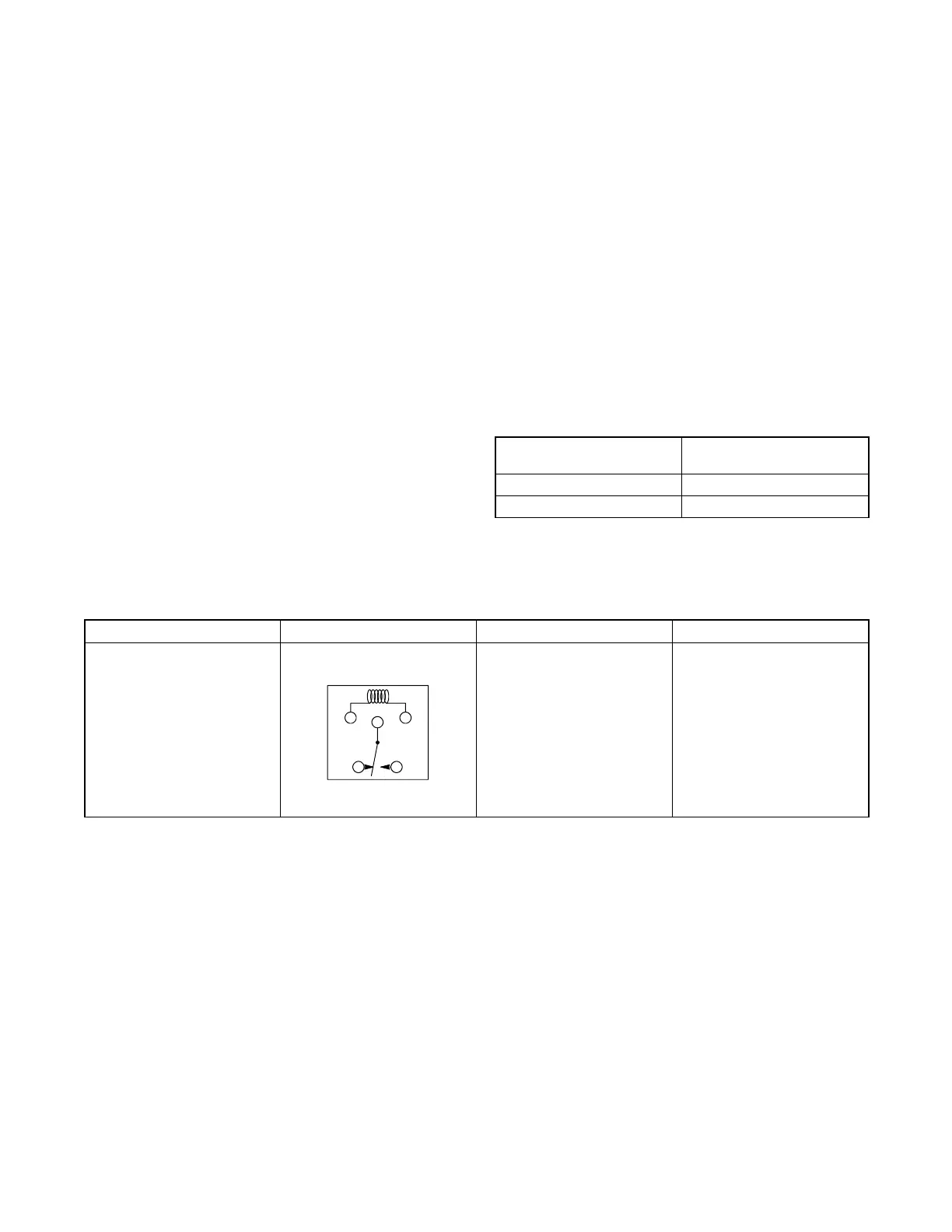
Component Ohmmeter Connections Remarks Results
K1, K2, K3, K4, Relay Coil K1 Coil Terminals (see relay
schematic)
Relay Schematic
OhmmeteronRx10
scale
If good, approx. 400 ohms.
Low resistance (continuity)
indicates a shorted coil. High
resistance indicates an open
coil.
Figure 4-9 Controller Circuit Board Component Test