TP-5867 11/02 39Section 6 Component Testing and Adjustment
Short circuits. Hazardous voltage/current can cause
severe injury or death. Short circuits can cause bodily injury
and/or equipment damage. Do not contact electrical
connections with tools or jewelry while making adjustments or
repairs. Remove all jewelry before servicing the equipment.
Grounding electrical equipment. Hazardous voltage can
cause severe injury or death. Electrocution is possible
whenever electricity is present. Open the main circuit
breakers of all power sources before servicing the equipment.
Configure the installation to electrically ground the generator
set, transfer switch, and related equipment and electrical
circuits to comply with applicable codes and standards. Never
contact electrical leads or appliances when standing in water
or on wet ground because these conditions increase the risk of
electrocution.
Voltage Regulator Adjustment Procedure
1. With the generator set off, turn the remote rheostat,
if equipped, and stability potentiometers to
midpoint. Turn the voltage and volts/Hz
potentiometers fully counterclockwise.
2. Connect a digital voltmeter from one side to the
circuit breaker to the L0 terminal inside the
controller assembly. See Figure 6-7. Set the meter
to measure voltage.
Note: For 120- or 240-volt systems the voltage
measured from one side of the breaker to L0
should be approximately 120 VAC. For
240-volt systems, the voltage measured
from one side of the circuit breaker to the
other should be approximately 240 VAC.
3. Start the generator set.
4. Rotate the voltage adjustment potentiometer
clockwise to increase voltage or counterclockwise
to decrease voltage until the regulator reaches the
desired output voltage.
5. Rotate the stability potentiometer clockwise until
the light flicker minimizes.
6. Readjust the voltage adjustment potentiometer, if
necessary.
7. Set the voltmeter to measure frequency. Adjust the
engine speed to the cut-in frequency shown in
Figure 6-8 by adjusting the speed potentiometer
on the electronic governor. See Section 6.9,
Electronic Governor. Rotate the potentiometer
counterclockwise to decrease the engine speed.
8. Set the voltmeter to measure voltage. Rotate the
volts/Hz adjustment potentiometer on the voltage
regulator clockwise until the voltage level
measured by the voltmeter begins to drop. When
set, the generator (as load is applied) attempts to
maintain normal output until the engine speed
drops below the cut-in frequency set in step 7.
Frequency Cut-In Frequency
60 Hz 57.5 Hz
50 Hz 47.5 Hz
Figure 6-8 Cut-In Frequencies
9. Set the voltmeter to measure frequency. Adjust the
engine speed to the operating frequency (50 or
60 Hz) by rotating the speed adjustment
potentiometer on the governor. Rotate the
potentiometer clockwise to increase the engine
speed.
10. Readjust the stability potentiometer on the voltage
regulator, if necessary.
11. Check the voltage. Readjust the voltage
adjustment potentiometer on the voltage regulator,
if necessary.
12. Stop the generator set.
6.4 Main Field (Rotor)
The two-pole rotor creates the magnetic field needed to
produce alternating current in the stator windings.
Before testing, inspect the rotor for visible damage to
pole shoes, insulation, exposed coil windings, and slip
ring surfaces. Rotate the bearing to check for wear, heat
discoloration, or noise.
6.4.1 Rotor Continuity and Resistance
Tests
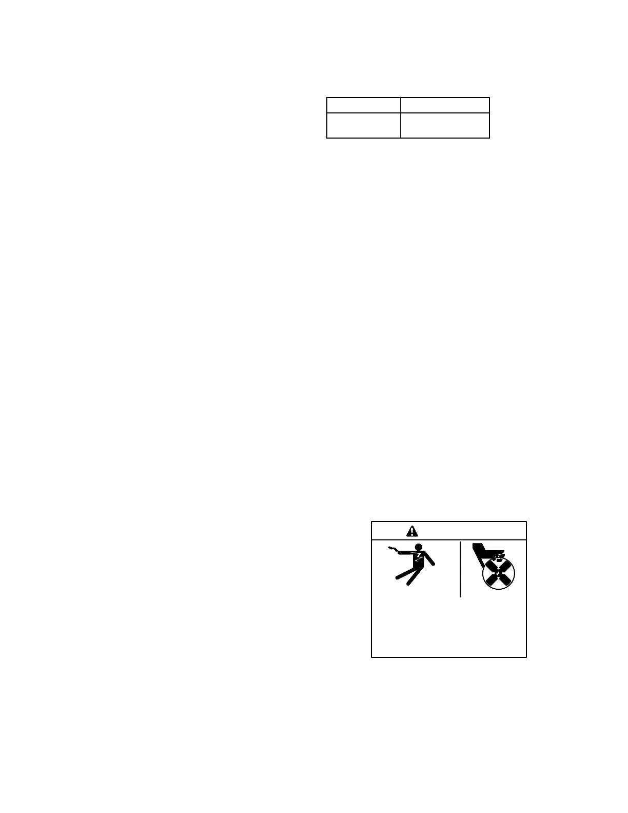
Hazardous voltage.
Can cause severe injury or death.
Operate the generator set only when
all guards and electrical enclosures
areinplace.
Moving rotor.
WARNING