TP-5867 11/02 57Section 6 Component Testing and Adjustment
Explosive fuel vapors.
Can cause severe injury or death.
Use extreme care when handling,
storing, and using fuels.
WARNING
Fuel Conversion Procedure for Multi-Fuel
Systems
1. Place the generator set master switch in the OFF
position.
2. Disconnect the power to the battery charger, if
equipped.
3. Disconnect the generator set engine starting
battery, negative (--) lead first.
4. Turn off the fuel supply.
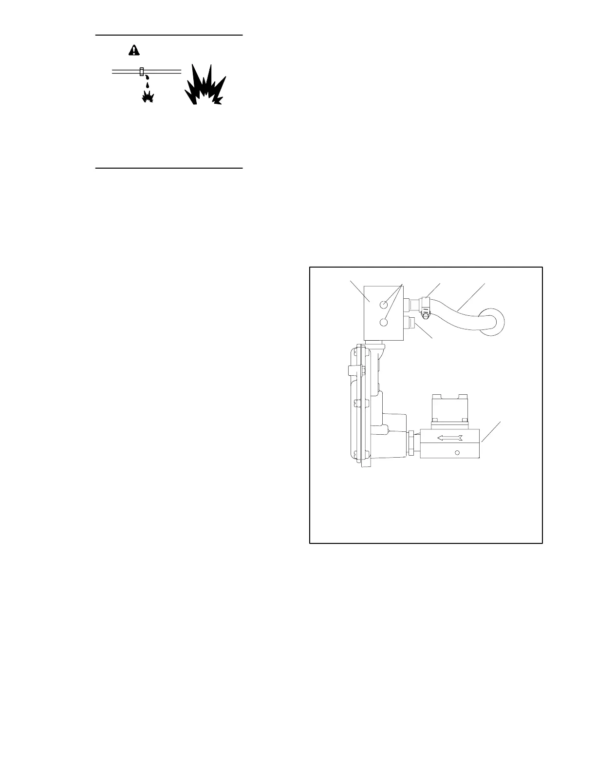
5. Remove the hose clamp and fuel hose from the
hose fitting in the fuel block. See Figure 6-31.
6. Remove the hose fitting from the natural gas (or
LP) outlet port in the fuel block.
7. Remove the plug from the LP (or natural gas) port
in the fuel block. Clean the plug with a dry cloth or
brush, apply fresh pipe sealant, and install the plug
into the natural gas (or LP) outlet port.
8. Clean the hose fitting with a dry cloth or brush,
apply fresh pipe sealant to the threads, and install
the fitting into the LP (or natural gas) port.
Note: Do not adjust the fuel metering valves.
9. Slide the hose onto the hose fitting and secure it
with the clamp.
10. Connect the new fuel supply.
11. Disconnect both wires at the fuel solenoid valve.
12. Apply ±12 VDC to the fuel solenoid valve to
actuate the valve.
13. Turn on the fuel supply and check for leaks at the
fuel block using a gas leak detector or a soap
solution.
14. Check that the generator set master switch is in the
OFF position.
15. Reconnect the generator set engine starting
battery leads, negative (--) lead last.
16. Reconnect power to the battery charger, if
equipped.
The secondary regulator operates with either natural
gas or LP gas with no modifications.
5
ADV-6600
1. Fuel block
2. Fuel metering valves— factory-sealed, do not adjust
3. Clamp
4. Fuel line hose
5. Plug
6. Fuel inlet, 1/2 in. NPT
OUT IN
LP
NG
1
42
6
3
Figure 6-31 Fuel Block Connections, Natural Gas
System Shown