30 TP-6694 9/20
1.2.5 Digital Display Circuit Board and Connections
The digital display circuit board provides:
The backlit LCD (liquid crystal display) for monitoring the generator set functions and output values
Master control switches with status lights
Fault lamp
Pushbutton/rotary selector dial to navigate the generator set displays
Alarm horn and alarm silence/lamp test switch/light
Mini USB connector for PC setup using SiteTech™ software
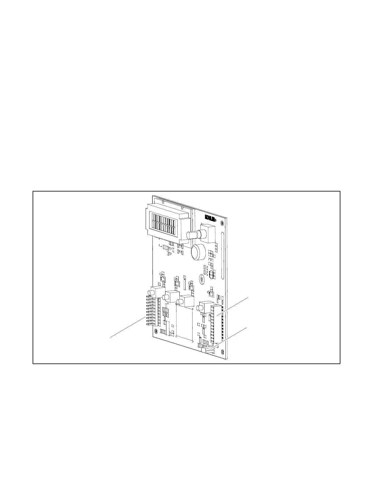
See Figure 4 Digital Display Circuit Board Connectors
Figure 4 for the circuit board connections.
Circuit Board Connections
P9 Connector the 24-pin connector attaches directly to the main logic circuit board.
P10 Connector mini USB for PC upgrades located on the front panel using SiteTech™ software.
P11 Connector is a 20-pin connector (not used).
Figure 4 Digital Display Circuit Board Connectors