102
Reassembly
KohlerEngines.com 62 690 13 Rev. A
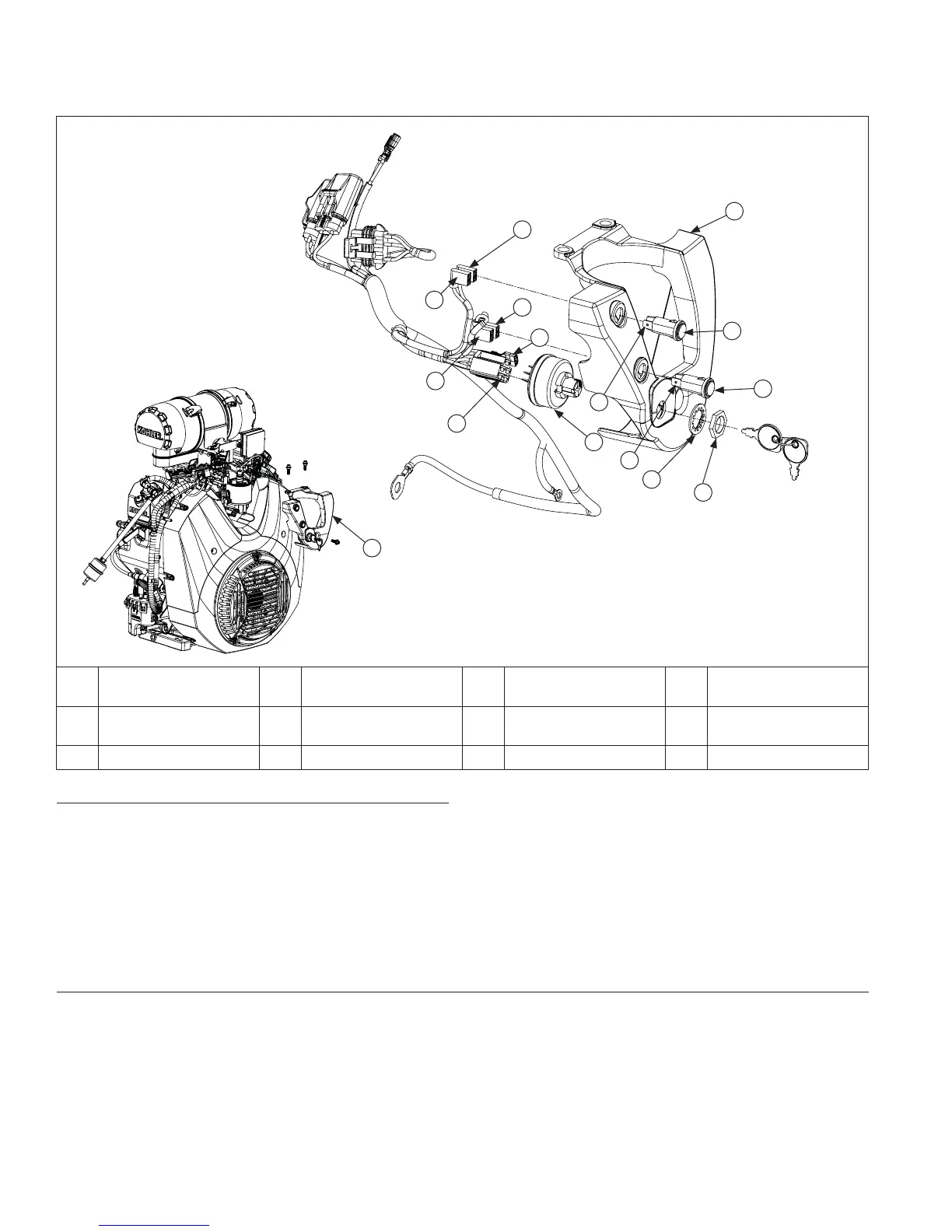
Control Panel Components
J
B
F
A
A
C
J
K
L
F
H
I
G
E
D
A Control Panel B MIL Indicator Light C
Oil Pressure
Indicator Light
D Nut
E Washer F
Indicator Positive
(Red Mark) Terminal
G Key Switch H 5-Pin Connector
I Ground Terminal J Yellow Wire K Tan Wire L Green Wire
Install Control Panel (if equipped)
1. If key switch was removed, install in control panel aligning slot in key switch housing with tab on control panel.
Secure key switch with washer and nut on outside of control panel. Torque nut to 1.6 N·m (14 in. lb.).
2. Connect ground terminal and 5-pin connector to key switch.
3. Connect yellow, tan, and green wires for Oil Pressure and MIL LEDs. Ensure yellow wires are connected to
positive (red mark) indicator light terminals.
4. Slide control panel up and over oil fi lter housing.
5. Install control panel to main control bracket and oil fi lter housing. Torque top 2 screws into intake manifold to
11.3 N·m (100 in. lb.). Torque bottom screw into oil fi lter housing to 11.3 N·m (100 in. lb.).
Install Muffl er
1. Install new exhaust gaskets onto exhaust studs.
2. Install port liners (if equipped). Attach muffl er and secure with nuts onto exhaust studs. Torque nuts to 24.4 N·m
(216 in. lb.).
3. If equipped, install any attaching hardware and brackets. Torque M6 screws to 9.9 N·m (88 in. lb.), and M8 screws
to 24.4 N·m (216 in. lb.).
4. Install oxygen sensor, torque to 50.1 N·m (37 ft. lb.), and connect to wire harness.
5. Install spark arrestor (if used).