96
Reassembly
KohlerEngines.com 62 690 13 Rev. A
Install Intake Manifold
Torque Sequence
2
3
4
1
1. Install new intake manifold gaskets so notched
section is inward and points toward fl ywheel side.
2. Install intake manifold to cylinder heads. Make sure
gaskets remain in proper position. Torque intake
manifold screws in 2 stages using sequence shown,
fi rst to 16.9 N·m (150 in. lb.), fi nally to 22.6 N·m (200
in. lb.).
3. Install throttle body studs into intake manifold if
previously removed. Use nuts, locked fl ange to
fl ange, and tighten each stud until bottomed/tight.
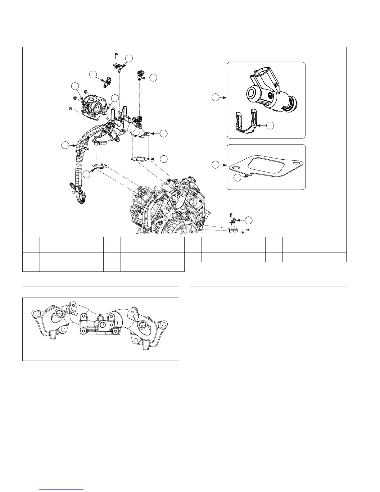
Intake Manifold Components
G
D
B
F
G
C
I
B
A
E
H
G
J
B
A
Crankshaft Position
Sensor
B
Intake Manifold
Gasket
C Intake Manifold D Fuel Rail
E TPS Sensor F Throttle Body G Fuel Injector H Metal Retaining Clip
I TMAP Sensor J Gasket Notch
Install Fuel Injectors
NOTE: Ensure all parts are clean, undamaged and free
of debris and make sure electrical connectors
have seal in place.
NOTE: O-rings and retaining clips should be replaced
any time fuel injector is separated from its
normal mounting position.
1. Lightly lubricate fuel injector O-rings with clean
engine oil.
2. Push retaining clip onto fuel injector, aligning clip as
shown.
3. Press fuel injector into fuel injector cap until retaining
clip snaps into place.
4. Press fuel injector into bore in intake manifold and
rotate to original position, as noted in Disassembly/
Inspection and Service.
5. Install fuel injector cap screw into intake manifold
and torque to 7.3 N·m (65 in. lb.).
6. Push electrical connector on fuel injector making
sure a good connection is made. Ensure injector
connector is in proper position based on
identifi cation steps made in Disassembly.
7. Repeat steps 1 through 6 for other fuel injector.