180 Section 9 Gas Fuel Systems TP-6356 4/12
Model,
kW
Engine
Straight Gas Fuel NG/LP Dual Fuel LP Liquid Withdrawal
LP, 60 Hz LP, 50 Hz NG, 60 Hz NG, 50 Hz 60 Hz 50 Hz 60 Hz 50 Hz
30
3.0 L 1--3 1--3, 2--3 none 2--3 none 2--3 1--3 1--3, 2--3
4.3 L
1--3, 2--5 1--3, 2--3 1--5, 2--5 1--5, 2--3 1--5, 2--5 1--5, 2--3 1--3, 2--5 1--3, 2--3
35
4.3 L
45
50
5.0 L
5.7 L
60 5.7 L
80
8.1 L 1--5 1--5, 2--5 none 2--5 none 2--5 1--5 1--5, 2--5
100
125
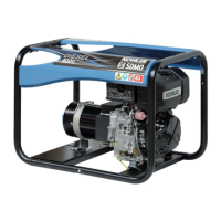
Figure 9-36 Fuel and Frequency Jumper Connections on TB12
a.
30--60 kW models.
D Remove the right side panel of the junction
box and locate the fuel configuration terminal
strip TB12.
D 30 kW model with 3.0 L engine only.
Attach a user-supplied 18 ga. jumper wire
between terminals 1 and 3 (LP gas vapor
fuel). See Figure 9-37 for frequency jumper
wire requirements.
Note: No jumper wire is used with natural
gas fuel.
30 kW model with 4.3 L engine and
35--60 kW models. Move the jumper wire
from terminals 1 and 5 (natural gas fuel) to
terminals 1 and 3 (LP gas vapor fuel). See
Figure 9-38 for frequency jumper wire
requirements.
D Attach the junction box right side panel.
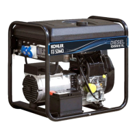
GM21300/GM21218
1. Junction box (rear view)
2. Fuel configuration terminal strip TB12
3. Jumper wire between terminals 1 and 3
(LP gas vapor fuel)
4. Frequency jumper wire
(60 Hz: none; 50 Hz: terminals 2 and 3)
12
3
4 not
used
Figure 9-37 Fuel Configuration Jumper Wire
(LP Fuel, 60 Hz, 30 kW [3.0 L] Model)
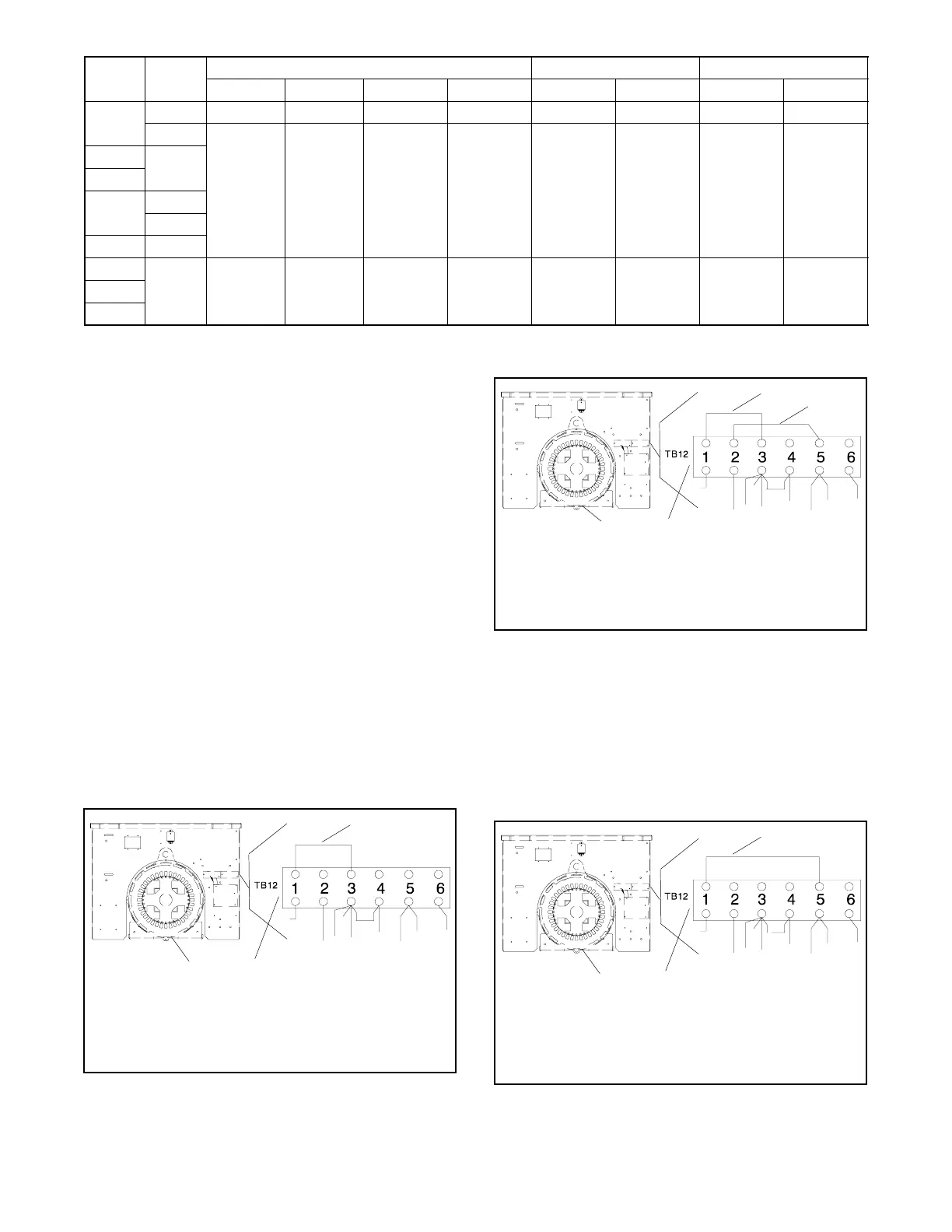
GM21300/GM21218
1. Junction box (rear view)
2. Fuel configuration terminal strip TB12
3. Jumper wire between terminals 1 and 3
(LP gas vapor fuel)
4. Frequency jumper wire
(60 Hz: terminals 2 and 5; 50 Hz: terminals 2 and 3)
1
2
3
4
Figure 9-38 Fuel Configuration Jumper Wire
(LP Fuel, 60 Hz, 30 kW [4.3 L] and
35--60 kW Models)
b.
80--125 kW models.
D Remove the right side panel of the junction
box and locate the fuel configuration terminal
strip TB12. See Figure 9-39.
GM21300/GM25000
1. Junction box (rear view)
2. Fuel configuration terminal strip TB12
3. Jumper wire between terminals 1 and 5 (LP gas vapor
fuel)
4. Frequency jumper wire
(60 Hz: no jumper; 50 Hz: terminals 2 and 5)
12
3
4 not
used
Figure 9-39 Fuel Configuration Jumper Wire
(LP Fuel, 60 Hz, 80--125 kW Models)