22 Section 1 Specifications TP-6356 4/12
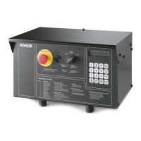
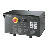
1.8 Decision-Makerr 550 with
Integrated Voltage Regulator
1.8.1 Features
D A digital display and keypad provide access to data.
A two-line vacuum fluorescent display provides
complete and concise information.
D The controller provides an interface between the
generator set and switchgear for paralleling
applications incorporating multiple generator set
and/or utility feeds.
D The controller can communicate with a personal
computer directly or on a network. See spec sheet
G6-76, Monitor III Software for more information.
D Using optional menu-driven, Windowsr-based PC
software, an operator can monitor engine and
alternator parameters and also provide control
capability.
D The controller supports Modbusr RTU (Remote
Terminal Unit), an industry standard open
communication protocol.
Voltage Regulator Menu 11 Displays
(DEC 550)
D Average voltage and voltage adjust
d Line-to-line voltage of each phase
D Under frequency unload enabled, yes/no
d Frequency setup
d Slope, volts per cycle
D Reactive droop enabled, yes/no
d Voltage droop %
D VAR control enabled, yes/no
d Total kVAR (running), kVAR adjustment
d Generating/absorbing yes/no
D Power factor control enabled yes/no,
droop at rated load 0.8 PF
d Average power factor (running), PF adjustment
d Lagging/leading, yes/no
D Regulator gain adjustment
D Utility gain adjustment
D Reset regulator defaults, yes/no
Modbusr is a registered trademark of Schneider Electric.
Windowsr is a registered trademark of Microsoft Corporation.
1.8.2 Specifications
Specifications/
Features
Voltage Regulator Type
Integral with DEC 550
Generator Set Availability 20--3250 kW
Type Microprocessor based
Status and Shutdown
Indicators
LEDs and Digital Display
Operating Temperature
-- 4 0 _Cto70_C(--40_F to 158_F)
Storage Temperature
-- 4 0 _Cto85_C(--40_F to 185_F)
Humidity 5--95% Non-Condensing
Circuit Protection
Solid-State, Redundant Software and
Fuses
Sensing, Nominal 100--240 Volts (L-N), 50--60 Hz
Sensing Mode RMS, Single- or 3-Phase
Input Requirements 8--36 VDC
Continuous Output 100 mA at 12 VDC
Maximum Output 100 mA at 12 VDC
Transition Frequency 50--70 Hz
No-Load to Full-Load
Voltage Regulation
±0.25%
Thermal Drift
<0.5%
(--40_Cto70_C)
[--40_F to 158_F] Range
Response Time Less Than 5μS
System Voltage Adjust. ±10%
Voltage Adjustment Controller Keypad
Remote Voltage
Adjustment
Digital Input Standard/
Analog 0--5 VDC Input Optional
Paralleling Capability Reactive Droop Std.
VAR/PF Control Input Standard
1.8.3 Settings
Calibration Digital Display Range Setting Default Selection
Voltage Adjustment VOL T ADJ ±20% of System Voltage System Voltage
Controller Gain REGULATOR GAIN 1--10000 100
Underfrequency Unload or
Frequency Setpoint
FREQUENCY
SETPOINT
40 to 70 Hz
1 Hz Below System Frequency (ECM)
2 Hz Below System Frequency
(non-ECM)
Underfrequency Unload Slope SLOPE 0--10% of Rated Voltage (Volts per Cycle) 15 Volts per Cycle at 480 Volts (3.1%)
Reactive Droop VOL TAGE DROOP 0--10% of System Voltage 4% of System Voltage
VAR Control KVAR ADJ --35% to 100% 0kVAR
PF Adjust Control PF ADJ --0.70 to 1.0 to 0.60 0.8 Lagging
VAR/PF Gain Adjustment VAR/PF GAIN 1--10000 100

 Loading...


