Manual EDU 2AE/TOP e EDU 2AE/TOP/TA Rev.1.1 Page 19
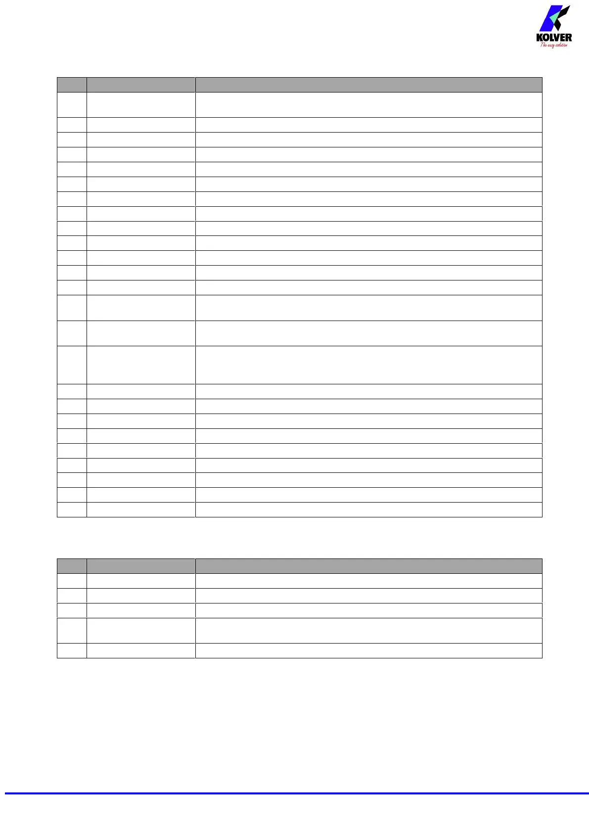
CN5 CONNECTOR (25 pin connector - female):
Common to every input. Signals have to be enabled making contact between
the desired signal and this pin (common 0VDC) .
It indicates stop motor is enabled
It indicates you’re using program 8
It indicates you’re using program 7
It indicates you’re using program 6
It indicates you’re using program 5
It indicates you’re using program 4
It indicates you’re using program 3
It indicates you’re using program 2
It indicates you’re using program 1
+24VPLC available on this pin, they can’t be used to charge external devices.
+5VDC available on this pin, it can’t be used to charge external devices
If enabled (see point 4: OK-ESC, in the option menu), remote OK key
function.
If enabled (see point 4: OK-ESC, in the option menu), ESC key function to
reset remote errors.
If enabled (see point 4: OK-ESC, in the option menu), it resets program or
sequence according to the preset function (see point 5: Reset, in the option
menu)
Switch – selection of program 8
Switch – selection of program 7
Switch – selection of program 6
Switch – selection of program 5
Switch – selection of program 4
Switch – selection of program 3
Switch – selection of program 2
Switch – selection of program 1
+15VCC available on this pin, not used to charge external devices
CN6 CONNECTOR (serial connector 9 pin - male) - FOR BARCODE CONNECTION
+15VCC available on this pin, it can’t be used to charge external devices.
Common to every input. Signals have to be enabled making contact between
the desired signal and this pin (common 0VDC).
+5VDC available on this pin, it can’t be used to charge external devices.