RANGE SELECTOR VALVE TRANSMISSION
7C - 93
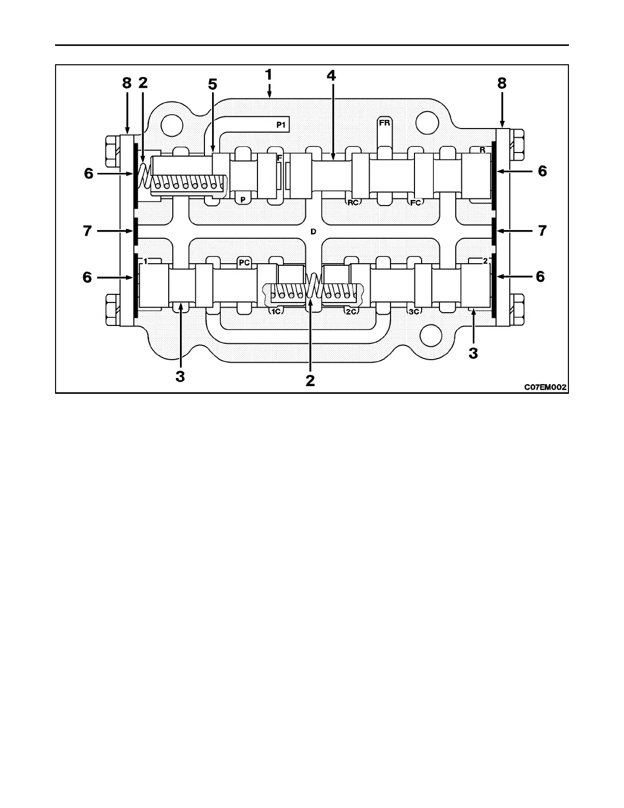
CROSS SECTION VIEW OF RANGE SELECTOR VALVE
1. Valve Housing
2. Speed Spool Return Spring
3. Speed Spool
4. Directional Spool - Long
5. Directional Spool - Short
6. Large O-Ring
7. Small O-ring
8. End Cover
9. Port Plug
DESCRIPTION
Range selector valve is a hydraulically controlled, directional control valve consisting of two speed spools and two
directional spools. Speed spools are separated in valve housing by a centering spring. Directional spools are held
together at one side by their return spring.
THEORY OF OPERATION
Function of range selector valve is to provide main pressure oil to rate of rise valve and return oil from rate of rise valve
to desired clutch packs. Valve is hydraulically controlled by pilot control valve. Short directional spool (5) controls flow
of oil to rate of rise valve. When in neutral, return spring (2) holds this spool (5) against long direction spool (4), thereby
cutting off flow of oil. When shift lever is placed in forward, main pressure oil from pilot control valve enters port F and
shifts spool (5) against return spring (2). When shift lever is placed in reverse, main pressure oil from pilot control valve
enters port R and shifts both spools (4 and 5) against return spring (2). Once short directional spool (5) is shifted over,
port P1 is open to port P, directing oil to rate of rise valve. Long direction spool (4) controls flow of oil to forward and
reverse clutch packs. When shift lever is in forward, main pressure oil from pilot control valve enters port F, holding long
directional spool (5) against end cover (8). When in this position, oil from rate of rise valve enters port FR, and is directed
out port FC to engage forward clutch shaft. When shift lever is placed in reverse, main pressure oil enters port R, shifts
spool (4) and port FR is opened to port RC to engage reverse clutch pack. Two speed spools (3) control flow of oil to
speed clutch packs. When shift lever is placed in first, main pressure oil from pilot control valve enters port 1, shifting
spool (3) against return spring (2). When in this position, oil from rate of rise valve enters port PC and is directed out port
1C to engage first speed clutch pack. When shift lever is placed in second, oil enters port 2 to shift spool (3) and port
PC is opened to port 2C to engage second speed clutch pack. When shift lever is in third, return spring (2) holds spools
(3) in place and port PC is opened to port 3C to engage third speed clutch pack.
 Loading...