SYSTEM RELIEF VALVE CONTROL VALVE
10B - 17
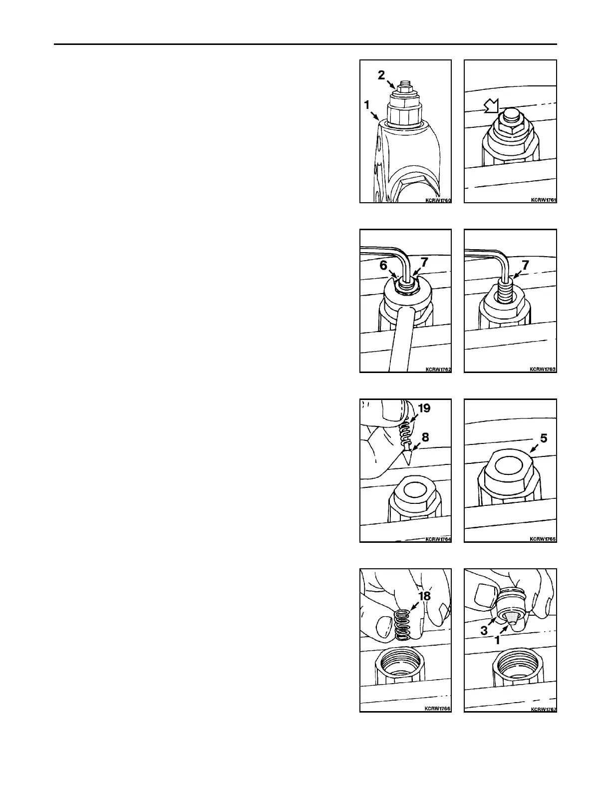
DISASSEMBLY
1. Remove system relief valve (2) from inlet cover (1).
REMARK
Callouts from exploded and cross section views correspond with
callouts in following steps.
2. Position relief valve in vise, adjusting end up.
3. While holding adjusting screw (7), remove jam nut (6).
4. Remove adjusting screw (7).
5. Remove pilot poppet (8) and spring (19).
6. Remove end cap (5).
7. Remove main poppet spring (18).
8. Remove main poppet (3) with filter screen (1).
 Loading...