24. SERVICE PROCEDURE
1.
2.
3.
4.
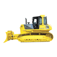
Remove the bolts and track adjuster cover.
To increase track tension, connect a lubricator nozzle to the lubrication
fitting (2). Determine the amount of adjustment necessary, and add lubricant
to obtain the proper track chain tension. It is advisable to move the machine
forward and backward slightly to be sure the correct tension has been
obtained.
To reduce track tension, loosen the bleeder valve (3) % to 1 full turn to allow
the pressurized lubricant to escape through the relief passage. If lubricant
does not appear, loosen the check valve (4) (located under the lubrication
fitting) % to one full turn to allow the pressurized lubricant to escape from a
second relief passage.
If lubricant still does not appear, use the following emergency method.
Should the relief passages still be blocked, unscrew the ball check and/or
relief valve an additional I-% to 2 turns (2-X total turns). This will allow a
greater amount of pressurized lubricant to free the passages.
A
WARNING
Use extreme care when relieving pressure with the following emergency
method. If loosened excessively, the ball check or relief valve can be
ejected by the cylinder pressure. NEVER
loosen these parts more than
a total of 24 turns.
1
5. When the proper tension has been obtained, tighten the ball check and/or
relief valve to value given below. Install the cover and secure with removed
hardware.
u Ball Check or Relief Valve:
REMARK
68 Nern (50 Ibf ft )
Never remove one link to bring a stretched track to within the range of
proper track adjustment. A track that is worn badly enough to take up the
length of one link, will be so far out of pitch that the increased wear on the
sprocket will far more than offset the saving obtained by the removal of one
link in the track chain.
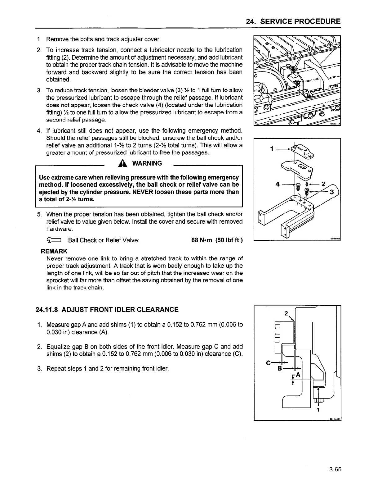
24.11.8 ADJUST FRONT IDLER CLEARANCE
Measure gap A and add shims (1) to obtain a 0.152 to 0.762 mm (0.006 to
0.030 in) clearance (A).
Equalize gap B on both sides of the front idler. Measure gap C and add
shims (2) to obtain a 0.152 to 0.762 mm (0.006 to 0.030 in) clearance (C).
Repeat steps 1 and 2 for remaining front idler.
L
3-65
 Loading...