UEN00663-02 50 Disassembly and assembly
8 PC210, 230, 240-8
Removal and installation of
control valve assembly
k Release the remaining pressure in the
hydraulic circuit. For details, see Testing
and adjusting, release of remaining pres-
sure in hydraulic circuit.
Removal
a Attach an identification tag to each piping to
avoid a mistake in the position of installation
later.
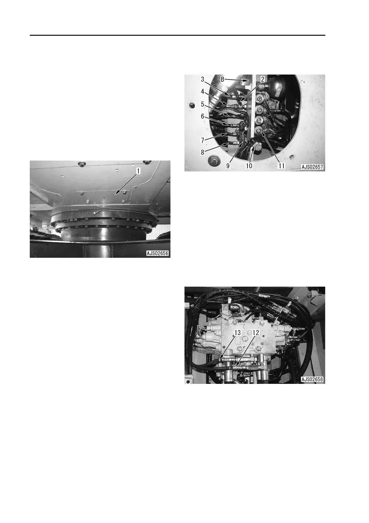
1. Remove cover (1).
2. Drain hydraulic tank oil.
a Make the swing speed almost 0 degree for
below (3. – 6.) and to remove the control
valve mounting bolt.
6 Hydraulic tank:
Approx. 234l (PC210, 230)
Approx. 239l (PC240)
a For the way not to drain the hydraulic tank
oil by using oil stopper, see Removal and
installation of hydraulic pump assembly.
3. Disconnect drain hose (2) through (8). Band:
q (2): No color
q (3): Red
q (4): No color
q (5): No color
q (6): Red and yellow
q (7): Brown
q (8): No color
4. Disconnect connector (9) from clip. From the
top,
V06
V05
V04
V03
V02
V01
5. Disconnect clamp (10).
6. Keep away solenoid assembly (11) from con-
trol valve bracket (B).
7. See Removal and installation of engine and oil
pressure pump assembly to remove below.
q Engine hood
q Control valve upper cover
q Cover between hydraulic pump and en-
gine
q Flame between control valve and engine
q Cover between control valve and engine
8. Disconnect PLS1 port hose (12).
a Hose band: No color
9. Disconnect PLS2 port hose (13).
a Hose band: red

 Loading...


