UEN00242-01 40 Troubleshooting
12 PC210, 230, 240-8
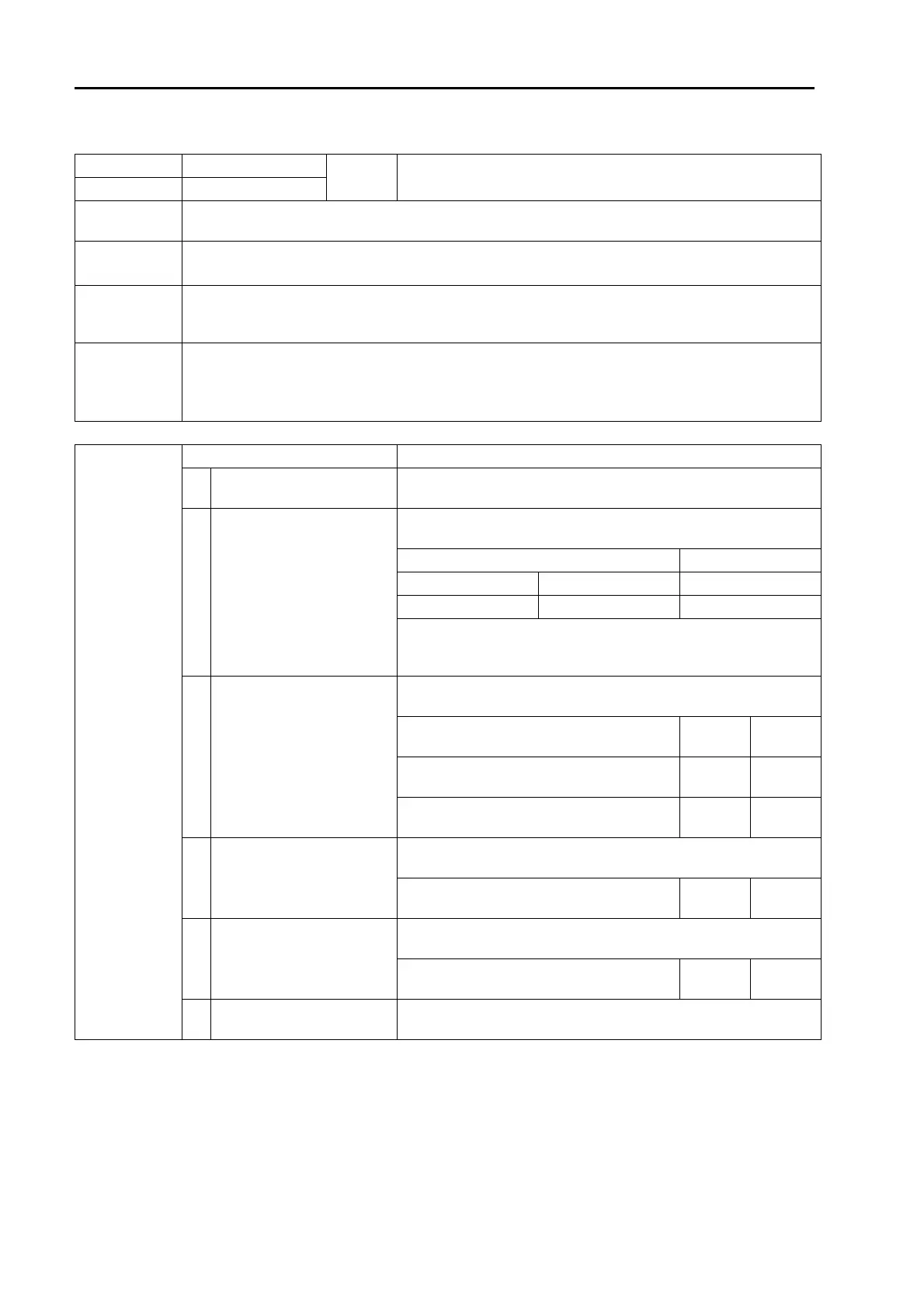
Failure code [DHPAMA] F Pump Press Sensor Abnormality 1
User code Failure code
Trouble
F pump pressure sensor abnormality
(Pump controller system)
— DHPAMA
Contents of
trouble
• Signal voltage of F pump pressure sensor circuit is below 0.3 V or above 4.5 V.
Action of
controller
• Fixes F pump pressure at 0 MPa {0 kg/cm
2
} and continues control.
• If cause of failure disappears, system resets itself.
Problem that
appears on
machine
• Automatic gear shifting function does not work.
• Straight travel performance or steering performance lowers.
Related infor-
mation
a If 5V circuit (3) and ground circuit (1) of pressure sensor are connected inversely, pressure sensor
will be broken. Accordingly, take extreme care when checking.
• F pump pressure can be checked with monitoring function. (Code: 01100 F pump pressure)
• Method of reproducing failure code: Turn starting switch ON or start engine.
Possible causes
and standard
value in normal
state
Cause Standard value in normal state/Remarks on troubleshooting
1
Defective 5V sensor power
supply 1 system
a If failure code [DA25KP] is also displayed, carry out trouble-
shooting for it first.
2
Defective F pump pressure
sensor (Internal defect)
a Prepare with starting switch OFF, then turn starting switch ON or
start engine and carry out troubleshooting in each case.
P25 Voltage
Between (3) – (1) Power supply 4.5 – 5.5 V
Between (2) – (1) Signal 0.3 – 4.5 V
If voltage is abnormal, replace F pump pressure sensor with R
pump pressure sensor and check failure code. (If "E" of failure code
goes off at this time, F pump pressure sensor is defective.)
3
Disconnection in wiring har-
ness (Disconnection in wiring
or defective contact in con-
nector)
a Prepare with starting switch OFF, then carry out troubleshooting
without turning starting switch ON.
Wiring harness between C01 (female) (18) –
P25 (female) (1)
Resis-
tance
Max. 1 z
Wiring harness between C01 (female) (49) –
P25 (female) (2)
Resis-
tance
Max. 1 z
Wiring harness between C01 (female) (9) –
J06 – P25 (female) (3)
Resis-
tance
Max. 1 z
4
Ground fault in wiring har-
ness (Short circuit with GND
circuit)
a Prepare with starting switch OFF, then carry out troubleshooting
without turning starting switch ON.
Wiring harness between C01 (female) (49) –
P25 (female) (2)
Resis-
tance
Min. 1 Mz
5
Hot short (Short circuit with
24V circuit) in wiring harness
a Prepare with starting switch OFF, then turn starting switch ON
and carry out troubleshooting.
Wiring harness between C01 (female) (49) –
P25 (female) (2)
Voltage Max. 1 V
6 Defective pump controller
If causes 1 – 5 are not detected, pump controller may be defective.
(Since trouble is in system, troubleshooting cannot be carried out.)

 Loading...


