30 Testing and adjusting UEN00228-04
PC210, 230, 240-8
29
the safety-suction valve of the control
valve for lowering the boom is
relieved).
a If the power maximizing switch is
released, the main relief valve is
relieved at low pressure. If the former
is pressed, the latter is relieved at
high pressure.
a If the swing lock switch is set in
turned ON, the 2-stage relief solenoid
valve is kept turned ON and the relief
valve is relieved at high pressure.
Accordingly, keep the swing lock
switch turned OFF.
5. Measuring swing relief pressure
1) Start the engine, set the working mode in
the power mode (P), and turn the swing
lock switch ON.
6. Run the engine at high idle, operate the left
work equipment control lever to relieve the
swing motor, and measure the oil pressure.
a The pressure measured when the
swing motor relief valve is relieved is
indicated.
a The swing relief pressure is lower
than the main relief pressure.
7. Travel relief pressure
1) Run the engine and lock the travel mecha-
nism.
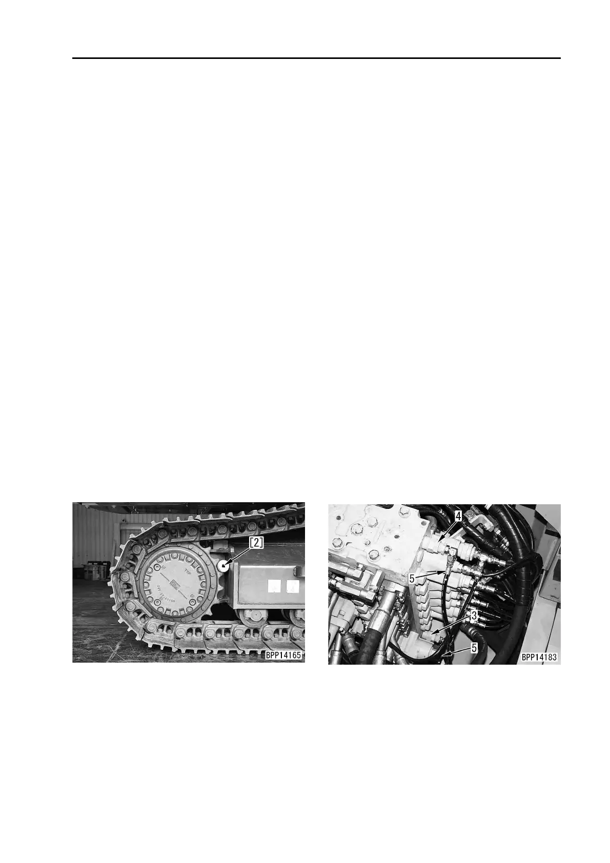
k Put pin [2] between the sprocket
and track frame to lock the travel
mechanism securely.
2) Set the working mode in the power mode
(P).
3) Run the engine at high idle, operate the
travel lever and pedal to relieve the travel
motor, and measure the oil pressure.
k Before operating the travel lever
and pedal, check the position and
locking direction of the locked
sprocket again.
a The pressure measured when the main
relief valve of the control valve is
relieved is indicated. The travel circuit
is always relieved at high pressure.
8. Work after finishing measurement
After finishing measurement, remove the
measuring tools and return the removed parts.
3 Oil pressure pickup plug:
20 – 27 Nm {2.0 – 2.8 kgm}
Adjusting
a The unload valve and safety-suction valve for
lowering the boom cannot be adjusted.
1. Adjusting work equipment and travel relief
pressure
a If the relief pressure of the work equip-
ment circuit and travel circuit is abnormal,
adjust main relief valves (3) and (4)
according to the following procedure.
q (3): Front (F) main relief valve
q (4): Rear (R) main relief valve
a When adjusting the main relief valves,
remove the top cover of the control valve.
a Adjust only the low relief pressure of the
main relief valve. If the low repair proce-
dure is adjusted, the high repair procedure
is set automatically.
a The low relief pressure is the pressure
applied when the 2-stage relief solenoid
valve is turned OFF and the pilot pressure
is not applied to the selector port.
1) Disconnect pilot hose (5).
2) While fixing holder (6), loosen locknut (7).
3) Turn holder (6) to adjust the set pressure.
a If the holder is
q Turned to the right, the set pres-
sure is increased.
q Turned to the left, the set pres-
sure is decreased.
a Quantity of adjustment per turn of holder:

 Loading...


