50 Disassembly and assembly UEN00662-00
PC210, 230, 240-8
13
Expansion and installation of
track shoe assembly
Special tools
Development of track shoe
1. Turn the upper structure by 90 degrees.
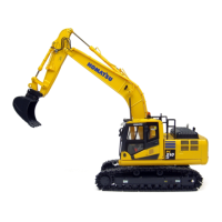
2. Loosening lubricator (1), slacken the tension of
track shoes. [*1]
k Since the inner pressure of adjusting
cylinder is extremely high, never loosen
the lubricator more than one turn. If the
grease does not come out smoothly,
move the machine back and forth.
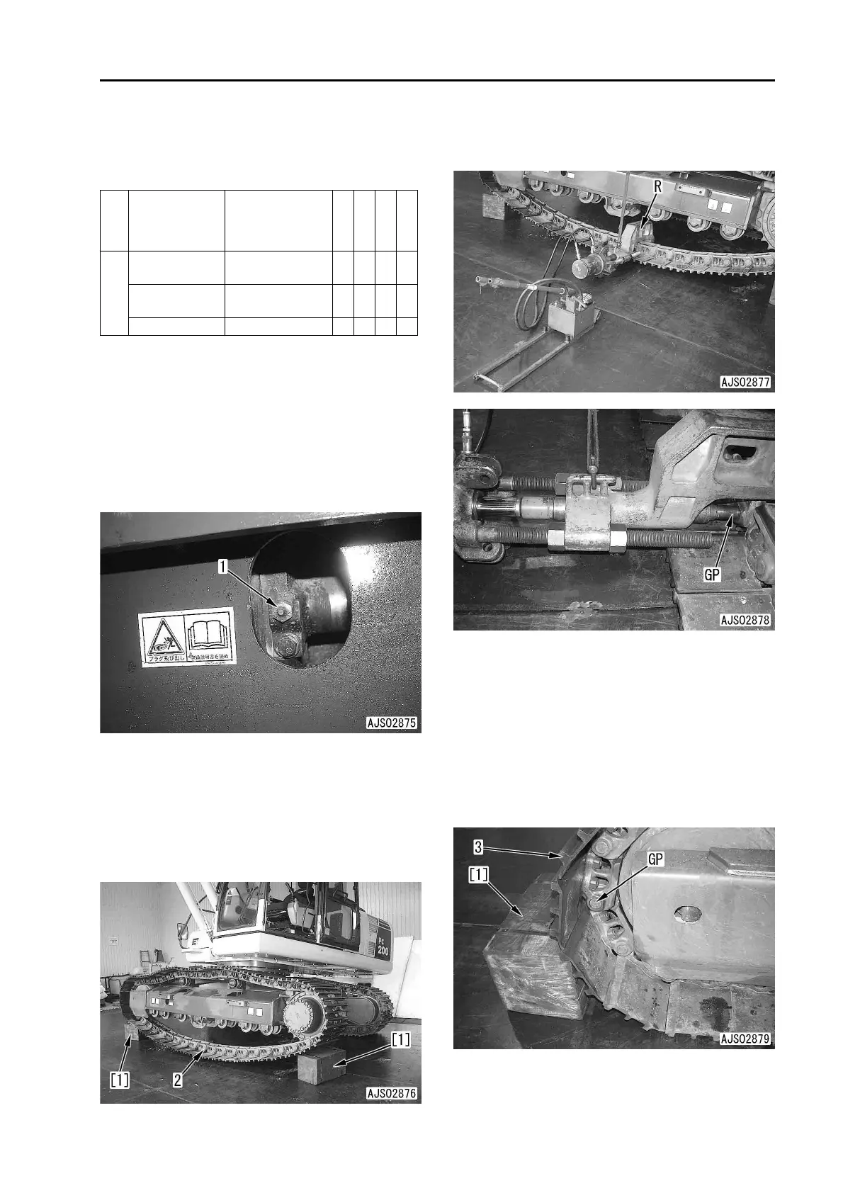
3. Set the location of master pin (2).
1) Pushing against ground with the work
equipment, lift the track shoes.
2) Locate master pin (2) at around the center
of lower track shoes and between two
track rollers.
3) Set blocks [1] under both track shoes at
idler and sprocket.
4. Using tool R, remove master pin (2). [*2]
a Press fit guide pin (GP), so that master pin
(2) will be pushed out.
5. Set the location of guide pin (GP).
1) Pushing against ground with the work
equipment, lift the track shoes.
2) Take away blocks [1] under both track
shoes at idler and sprocket.
3) Bring guide pin (GP) at the front of the idler.
4) Relieve the work equipment, and lower
the machine body.
5) Set block [1] under track shoe (3) at front
of the idler.
Symbol
Part number Part name
Necessity
Q’ty
N/R
Sketch
R
791-630-3000
Remover and
installer
t 1
790-101-1300
Cylinder
(980kN{100ton})
t 1
790-101-1102 Pump t 1