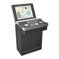
The K-Pos Human Machine Interface (HMI) is a comprehensive control system designed for dynamic positioning (DP) operations. It provides a user-friendly interface for operators to manage and monitor various aspects of a vessel's position, heading, and thruster control. The system is built around an operator panel and a display interface, offering both tactile and visual feedback for efficient operation.
Operator Panel
The operator panel is the central hub for manual control and system interaction. It features a dedicated DP panel with numerous push buttons, most of which include status lamps to indicate their active state. This allows for quick visual confirmation of selected functions, modes, and systems. The panel also incorporates a command and alarm panel, providing immediate access to critical system information and alerts.
For precise input, the operator panel includes a keypad for numeric data entry, a trackball for cursor manipulation, a 3-axis joystick for direct vessel control, and a heading wheel with associated buttons for heading adjustments. These input devices are strategically placed to facilitate intuitive and efficient operation.
Push buttons on the operator panel are categorized by their main function, enhancing usability. They are used to activate main modes, position-reference systems, thrusters, and various other functions. Status lamps accompanying these buttons provide clear visual feedback on their activation status. For safety, certain critical buttons require a double press within four seconds to invoke an action, indicated by a white line along their lower edge.
- Mode Buttons: This group allows operators to select the primary operational modes of the DP system. Status lamps indicate the currently active mode. Additionally, three buttons enable individual axis selection (surge, sway, and yaw) for automatic control.
- Controls Buttons: This group provides access to various system functions and dialog boxes, allowing for fine-tuning and configuration of the DP system.
- Views Buttons: These buttons are used to select the specific display view to be shown in the main working area of the screen, enabling operators to quickly switch between different information displays.
- Thrusters Buttons: This group contains buttons for enabling and managing individual thrusters, allowing operators to control the vessel's propulsion system.
- Sensors Buttons: These buttons are used to enable position-reference systems and to open dialog boxes related to other system sensors, ensuring accurate data input for DP operations.
- Command Buttons: This group facilitates the transfer of command between different operator stations or terminals, ensuring seamless control transitions.
Alarms
The ALARMS button group provides indicators and buttons for displaying and acknowledging alarms and events. The SILENCE button allows operators to silence audible signals without acknowledging the underlying Emergency or Alarm message.
- Alarm Lamps:
- POWER: Lit green when the operator panel's power supply is normal.
- FAULT: Lit red when communication between the operator panel and the Operator Station computer is lost.
- ALARM: Flashes for unacknowledged Emergency, Alarm, or Warning messages (e.g., heading or position deviation beyond limits). A continuously lit lamp indicates all messages are acknowledged. It extinguishes three seconds after the error status is cleared.
The INPUT keypad is used for entering values or text into dialog boxes. It can toggle between numeric and alphanumeric modes. Numeric mode is the default, and pressing the "abc..." button for one second switches to alphanumeric mode. A short beep confirms the change, and a green lamp indicates alphanumeric mode. In numeric mode, pressing a key enters the corresponding number. In alphanumeric mode, pressing a key multiple times cycles through the letters associated with that key. The ENTER key applies the entered value or text to the system.
Trackball
The TRACKBALL is used to position the cursor on the screen. The left button is used for clicking on screen buttons, selecting menu items, and choosing displayed symbols. The right button displays a shortcut menu. The middle button is not used.
Joystick
In Joystick mode, the operator controls the vessel's position using a three-axis joystick. Tilting the joystick moves the vessel in surge and sway directions, with the tilt angle determining the applied thruster force. Rotating the joystick controls the vessel's yaw axis, with the rotation angle determining the rotational moment demand.
Heading Wheel
The Heading Wheel, along with its seven buttons, is used for setting and adjusting the vessel's heading. Its functions vary depending on the active mode.
- HEADING (DECREASE/ACTIVATE/INCREASE): These buttons, in conjunction with the heading wheel, allow for changing the heading setpoint.
- HEADING WHEEL: Used for setting a new heading.
- RATE OF TURN/TURN RADIUS: Used for adjusting the rate of turn or turn radius.
- DISTANCE TO TURN: Used for adjusting the distance to turn.
Display Layout
The display interface utilizes standard Microsoft Windows operating features, including menus and dialog boxes. The display is divided into predefined areas, with dialog boxes appearing as needed for operator interaction.
- Title Bar: Identifies the K-Pos DP operator station, displays the current date and time, and shows the simulation status and delivery name. When the operator station has command, the Controller PS group and Command group fields have a yellow background. If the Trainer is used, "SIMULATING" flashes.
- Menu Bar: Provides command menus for accessing various dialog boxes. Commands may be active or unavailable depending on the current mode, with unavailable commands appearing dimmed.
- System Messages: System messages are color-coded for quick identification: EMERGENCY (magenta), ALARM (red), WARNING (yellow), and INFORMATION (grey).
- Message Line: Displays the most recent unacknowledged Emergency, Alarm, or Warning message. Right-clicking the message text opens the System Messages Help.
- Event List Window: Accessible via the ALARM VIEW button, this window lists all current system messages. Unacknowledged messages are marked with an asterisk (*) and a flashing background.
- Operator Advice Messages: Pop-up messages superimposed on the display provide advice when a button is pressed without command or when an invalid function is attempted. These messages are categorized by icons: ALARM (red 'X'), WARNING (yellow triangle), and INFORMATION (blue 'i').
- PUIF Monitoring: Monitors the Process Unit Interface, alarming if no K-Pos DP Process Stations are running. Dialog boxes indicate network response status.
- Performance Area: Displays critical performance information for immediate situation assessment. Its content changes automatically based on the selected main mode. Many parts of this area are click-sensitive, changing the cursor to a pointing hand and displaying a tooltip with an explanation.
- Force Balance Area: Indicates thruster turning moment (green bar), thruster force direction and magnitude (green arrowhead), wind direction and force (purple arrowhead), and sea current direction and force (blue arrowhead). Clicking this area displays the thruster main view.
- Position and Speed Area: Shows the present position and true speed (relative to the ground) in both forward/aft (surge) and port/starboard (sway) axes. Clicking these values displays position setpoints.
- Position Deviation / Joystick Setpoint Area: Clicking this area opens the Alarm Limits dialog box.
- In Auto Position mode and Joystick mode with automatic position control: Shows position deviation as a filled circle, with radius representing deviation, a number indicating distance to setpoint, and color changing based on warning/alarm limits (Green: inside, Yellow: outside warning, Red: outside alarm). A plus (+) sign indicates deviation exceeds display range, and an arrow shows if deviation is decreasing (green) or increasing (pink).
- In Joystick mode: Displays joystick setpoint in surge/sway graphically and numerically (purple bars), with feedback shown by green bars. The filled purple circle and dashed lines indicate joystick tilt.
- In Joystick mode with single-axis automatic control: Displays joystick setpoint and response for the controlled axis, and position deviation for the automatic axis as a two-directional bar, with color changing based on warning/alarm limits.
- Heading Deviation / Joystick Setpoint Area: Clicking the "compass" area opens the Sensors dialog box; clicking the "deviation" area opens the Alarm Limits dialog box.
- In Auto Position mode and Joystick mode with automatic heading control: Shows heading deviation graphically and numerically, with a two-directional bar indicating deviation from setpoint. Color changes based on warning/alarm limits. A plus (+) sign indicates deviation exceeds display range, and an arrow shows if deviation is decreasing or increasing.
- In Joystick mode: Displays turning force setpoint and vessel response (two-directional bars and numeric value), joystick rotation (purple arrow), and obtained turning moment (green bar and numeric value).
- Power Area: Shows consumed power for each main bus graphically as a percentage of available power. Dynamically updated to show current bus topology. Clicking this area displays the Power view.
- Gyro/Wind/VRS and Reference Systems Area: Displays status for gyrocompasses, wind sensors, VRSs, thrusters, and position-reference systems. Orange lamps and text indicate disabled gyrocompasses/sensors or insufficient thrust. Position offset for each reference system is shown as a pink bar. Clicking sensor indicators displays the Sensors View; clicking reference systems displays the Refsys Status View.
Working Areas
The working areas display operator-selectable views. These views provide detailed information on various aspects of the vessel's operation:
- Deviation view: Graphical and numerical performance data related to position and heading deviation.
- General view: Combination of graphical and numerical performance data.
- Joystick view: Thrust setpoint and response during Joystick mode.
- LTW view: Performance of a Light-Weight Taut Wire (LTW) position-reference system.
- Numeric view: Performance data in numerical form.
- Performance area: Important performance information for immediate situation assessment.
- Posplot view: Vessel's position and heading.
- Power view: Mimic display of the vessel's electrical power system.
- Power Consumption: Available and consumed power for each main bus.
- Refsys view: Individual and consequent performance of active position-reference systems.
- Refsys Status view: Status for each position-reference system or transponder.
- Rotation Centers view: Position of all available rotation centers under automatic control.
- Sensors view: Performance and state of vessel's sensors (gyrocompasses, wind sensors, VRS).
- Thruster views: Main and sub-views showing how the system uses thrusters to provide the required thrust setpoint, with setpoint/feedback data.
- Trends view: Dynamic displays (trend plots) and numerical values for historical data.
- Capability view: Results of the latest DP Capability Analysis.
- Motion Prediction view: Results of the latest Motion Prediction Analysis.
- Conning view: Useful information in Autopilot mode, especially during transit and maneuvering.
Selecting a Display View
Views can be selected in three ways:
- Using buttons in the VIEWS group on the panel.
- Clicking a view hotspot in the performance area.
- Placing the cursor in the desired area and clicking the right trackball button to display a shortcut menu.
In many display views, the cursor changes to a pointing hand (hotspot cursor) when moved over a click-sensitive area. A yellow tooltip frame appears, explaining the object's function. This feature can be toggled on/off via the View menu.
View Control Dialog Boxes
Many views have control dialog boxes for selecting displayed information and controlling view features. These are accessed via the shortcut menu. To open a dialog box, place the cursor in the view, click the right trackball button, and select "View Control." If a view has no associated dialog box, "View Control" will be unavailable.
Zooming
To zoom, place the cursor in the desired area, click the right trackball button, and select from the shortcut menu:
- Zoom In: Zooms the view, centered on the cursor position.
- Zoom Reset: Returns the view to its original scale.
- Center Here: Pans the view to center on the cursor position.
A zoomed view can be panned or zoomed further.
Status Bar
The status bar provides general system status information through click-sensitive indicators. Moving the cursor over an indicator changes it to a pointing hand, and clicking it opens a related dialog box.
- MainMode: Current operational mode.
- PosMode: Automatic position control mode (PRESENT or NEW SETP).
- HdgMode: Automatic heading control mode (PRESENT, SYS SEL or NEW SETP).
- AllocMode: Current thruster allocation mode (e.g., VARIABLE).
- RotCenter: Current Rotation Center.
- Refs: Status of position-reference systems (Grey: no PRS enabled; Yellow: at least one PRS enabled but not accepted; Green: at least one PRS enabled and accepted).
- Joystick: Current joystick settings (Thrust level: Full or Reduced; Precision level: High Speed, General or Low Speed).
- AutoPos: Graphic indications of axes under automatic control or damping control (surge, sway, yaw).
- Gain: Current controller gain level.
- DP Consequence Class: Currently selected DP Class for Online Consequence Analysis (Grey: Off; 2: Class 2; 3: Class 3).
Dialog Boxes
Dialog boxes are used to enter data or verify statuses and selections. They can be opened via panel buttons, menu commands, or by clicking graphical symbols/icons. Dialog boxes appear in the display area and can be moved. When data is modified, "(Changed)" is added to the title bar. Data is applied by clicking "Apply" or "OK."
- OK: Applies changes and closes the dialog box. If errors are found, no changes are made, and the box remains open.
- Cancel: No changes are made, and the dialog box closes.
- Apply: Applies changes, removes "(Changed)" from the title bar, and the dialog box remains open.
If changes are not allowed (e.g., operator station not in command), "OK" and "Apply" buttons are dimmed. It is recommended to use the "OK" button for direct feedback.