KRAMER: SIMPLE CREATIVE TECHNOLOGY
Connecting the 711N and the 712N
6
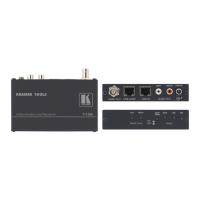
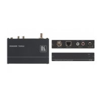
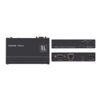
Table 2: 712N Video-Audio Line Receiver Features
# Feature Function
1 VIDEO OUT BNC Connector Connect to the composite video acceptor
2 LINE LOOP CAT5 Connector Connect to the LINE IN RJ-45 connector of an additional
receiver to increase the number of outputs
3 LINE IN CAT5 Connector
Connect to the LINE OUT RJ-45 connector of the 711N
4 LEFT RCA
Connector
Connect to the left unbalanced stereo audio acceptor
5
AUDIO
OUT
RIGHT RCA
Connector
Connect to the right unbalanced stereo audio acceptor
6 12V DC +12V DC connector for powering the unit
7 LEFT Trimmer Turn to adjust the left audio signal level
8
AUDIO
LEVEL
EQ. Trimmer Turn to adjust the output video signal equalization
1
12 ON LED Lights when receiving power
5 Connecting the 711N and the 712N
You can use the 711N and 712N to configure a Video-Audio Transmitter and
Receiver system.
To connect the 711N Video-Audio Line Transmitter with the 712N Video-
Audio Line Receiver, as illustrated in the example in Figure 5, do the
following:
1. Connect a composite video source (for example, a composite video player) to
the VIDEO IN BNC connector on the 711N, and connect an unbalanced
stereo source to the AUDIO IN RIGHT and LEFT RCA connectors.
2. On the 712N, connect the VIDEO OUT BNC connector to a composite video
acceptor (for example, a display).
3. Connect the LINE OUT connector of the 711N to the LINE IN connector of
the 712N, via UTP cabling.
4. If an additional output is required, connect the LINE LOOP connector on the
712N to the LINE IN connector of an additional 712N unit
2
, via UTP cabling.
5. On each 711N / 712N unit, connect a 12V DC power adapter
3
to the power
socket and connect the adapter to the mains electricity.
1 Insert a screwdriver into the hole and carefully rotate it, to trim the level
2 By connecting the LINE LOOP connector of the additional 712N to the LINE IN connector of a third 712N, you can further
increase the number of outputs
3 See section 3.1 for the power connect feature