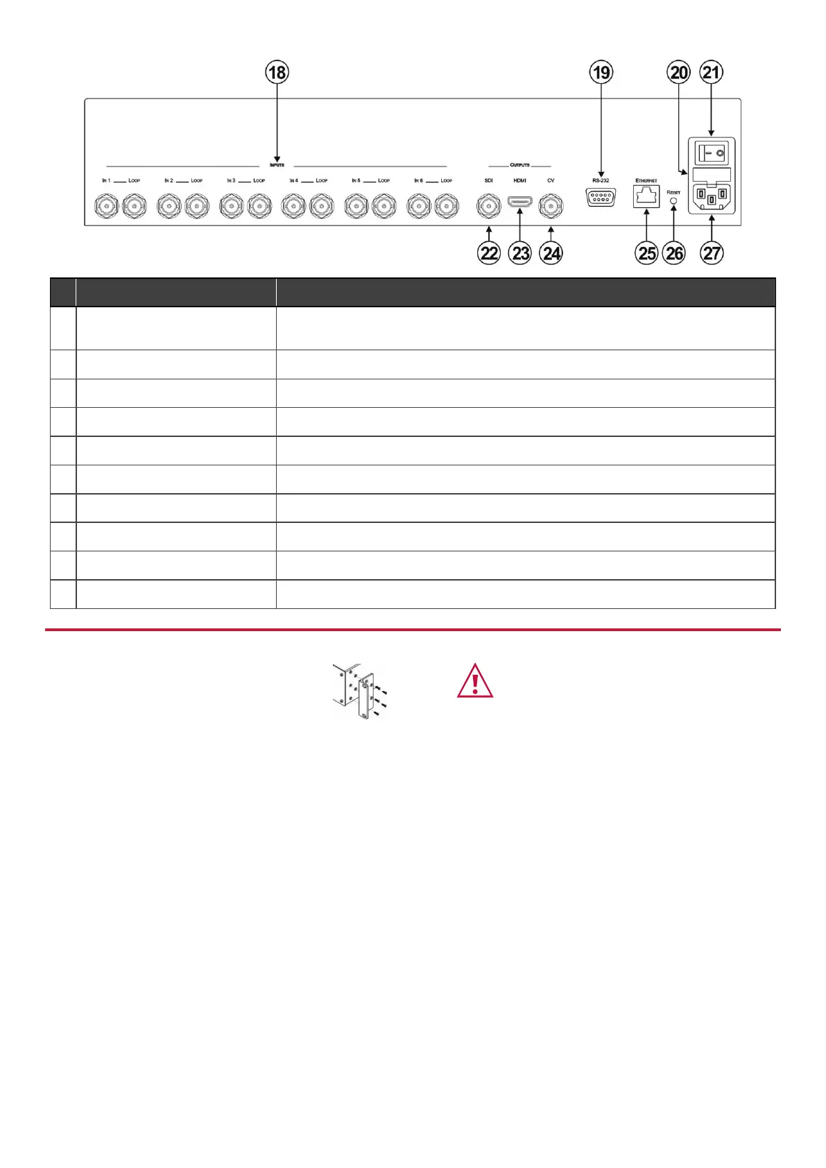
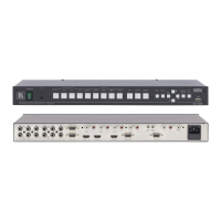
INPUTS (1 to 6) and Associated
BNC LOOP Outputs (1 to 6)
Connect inputs to video sources and loop outputs to loop video acceptors.
RS-232 9-pin D-sub (F) Connector
Connect to the serial port on a PC or remote control.
Fuse for protecting the device.
Switch for turning the device ON or OFF.
OUTPUTS SDI BNC Connector
Connect to an SDI video acceptor.
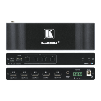
Connect to an HDMI video acceptor.
Connect to a composite video acceptor.
Connect to a PC via a LAN for remote control.
Press and hold while power cycling the device to reset to factory default configuration.
Connect to the mains power.
To rack mount the machine, attach both rack ears
(by removing the screws from each side of the
machine and replacing those screws through the
rack ears) or place the machine on a table.
• Ensure that the environment (e.g., maximum ambient temperature &
air flow) is compatible for the device.
• Avoid uneven mechanical loading.
• Appropriate consideration of equipment nameplate ratings should be
used for avoiding overloading of the circuits.
• Reliable earthing of rack-mounted equipment should be maintained.