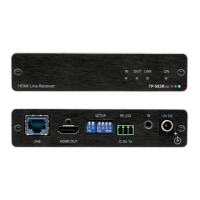
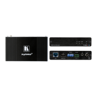
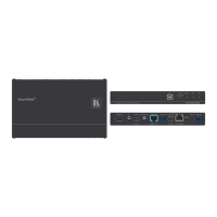
TP-583Txr, TP-583Rxr, TP-583T, TP-583R – Connecting the extenders
Controlling TP-583Txr
The DIP-switches are used to:
• Set the HDBT range (applicable to TP-583Txr and TP-583Rxr only).
• Set the compression levels and resolutions.
• Enable RS-232 signal extension.
• Determine IR signal pass-through modes.
Figure 4: [Figure Caption]
All the DIP-switches are set to OFF (up) by default.
To use your TP-583Txr or TP-583Rxr with any other standard HDBaseT extender (without
compression), verify that DIP-switch 1B is OFF (up).
OFF (up) – HDBaseT normal range.
ON (down) – HDBaseT ultra-long range (to enable increased
range at a reduced bandwidth).
The ultra-long range mode is activated when on at least
one of the devices DIP-switch 1 is set to ON.
Set Compression Level
(for Extended Range)
OFF (up) – Standard compression level.
ON (down) – High compression level for additional extension.
B – DIP-switch Settings
Changes to DIP-switches 2B and 3B only take effect after power cycling the device.
Define Compressed
Resolutions
OFF (up) – Compress signal resolutions higher than 1080p.
ON (down) – Compress all signal resolutions to enable extended
reach.
OFF (up), OFF (up) – Embed RS-232 data and control signals
over the extension line.
Other DIP-switch settings are reserved for firmware
upgrade.
For further details, contact support@kramerav.com.
OFF (up) – Pass-through the IR signal to the IR port via IR cable.
ON (down) – Add IR modulation to the IR output signal (applies
only when the IR port is connected to an IR emitter cable).
The IR Pass-through DIP-switch setup depends on the IR
control configuration. We recommend that you test which
position best suits your application.