7
4 Covered by a cap. The 3.5mrn connector at the end of the internal IR connection cable fits through this opening
5 Optional. Can be used instead of the front panel (built-in) IR receiver to remotely control the machine (only if the internal
IR connection cable has been installed)
6 Model: C-A35M/IRR-50
7 Model: C-A35M/A35F-50
8
PIN:
505-70434010-S
1 illuminates when selected and there is a signal
2 illuminates when configuring the EDID
3 Via a null-modem connection
You can use the RC-IR2 IR transmitter to control the machine via the
built-in IR receiver on the front panel or, instead, via an optional external IR
receiver",
The external IR receiver can be located 15 meters away from the
machine. This distance can be extended to up to 60 meters when used with
three extension cables
7.
Before using the external IR receiver, be sure to arrange for your Kramer
dealer to insert the internal IR connection cable" with the 3.5mm connector
that fits into the REMOTE IR opening on the rear panel. Connect the
external IR receiver to the REMOTE IR 3.5mm connector.
4.1 Using the IR Transmitter
#
Feature Function
1 IR Receiver The red LED is illuminated when receiving signals from the Kramer
infrared remote control transmitter
2 POWER Switch Illuminated switch for turning the unit ON or OFF
3
SELECT
IN 1Button'
Press to select source 1 and distribute this signal to the outputs
I---
IN2Button'
Press to select source 2 and distribute this signal to the outputs4
5
REAfi Press, after pressing the EDID SELECT button, to acquire the EDID
EOID Buttons
Press to show the EDID status
~ SELECT Select the EDID mode (One Output, Auto-mix or Default)
7
OUTPUT STATUS LEDs LEDs light when an output(s) is connected and active; LEDs flash to
indicate the type of EDID acquired (see section 6A) or when
connecting a non-HDCP display while providing HDCP content to
the VM-24H
8
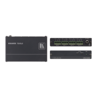
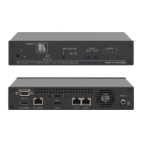
INPUT 1HDMI Connector Connects to the HDMI source 1
9 INPUT 2 HDMI Connector Connects to the HDMI source 2
10 OUTPUTHDMI Connectors Connects to the HDMI acceptor (from 1to 4)
11
RS-2329-pin D-sub Port Connects to the PC or the Remote Controller'
12 REMOTE IROpening4 Connects to an external IR receiver unit for controlling the machine
via an IR remote controller instead of using the front panel IR
receivers
13 Power Connector with Fuse AC connector enabling power supply to the unit
Table 1: VM-24H 2 Input 1:4 HDMI Distributor Features
Your VM-24H 2 Input 1:4 HDMI Distributor