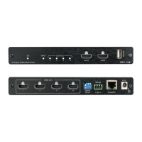
Step 4: Connect inputs and outputs
The three devices in this 6x2 diagram are designated 0, 1 and 2. Each output is designated by the device number and its
outputs. For example, VW-4 (1) is the second device in this video wall configuration and VW-4 (1-2) is HDMI OUT 2 on that
device.
Step 5: Connect power
Connect the power adapter to VW-4 and plug it into the mains electricity.
Safety Instructions (See www.kramerav.com for updated safety information)
Caution:
• For products with relay terminals and GPI\O ports, please refer to the permitted rating for an external connection, located next to the terminal or in the User Manual.
• There are no operator serviceable parts inside the unit.
Warning:
• Use only the power cord that is supplied with the unit.
• Disconnect the power and unplug the unit from the wall before installing.
Configure VW-4 via:
• DIP-switch settings – for basic
video wall configuration.
• VW-4 app, via the Ethernet or
RS-232.
• Remotely, by RS-232 serial
commands transmitted by a
touch screen system, PC, or
other serial controller.
RS-232 Control / Protocol 3000
Example: (Set Auto-sync Off to Fast): #SCLR-AS 1,2
Default Ethernet Parameters