Joint Line
Face Side
Large Pad
2
STEP 2 - Prepare workpieces and drill the pocket holes.STEP 2 - Prepare workpieces and drill the pocket holes.
STEP 2 - Prepare workpieces and drill the pocket holes.STEP 2 - Prepare workpieces and drill the pocket holes.
STEP 2 - Prepare workpieces and drill the pocket holes.
3
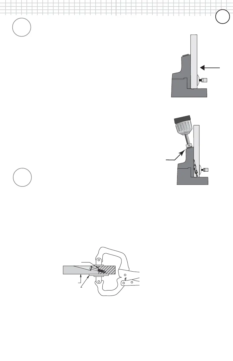
Prepare materials by squaring the pieces to be joined on
all edges. Place the drill bit into your drill and tighten
securely. Place one workpiece to be joined onto the base
of the K2000 Kreg Jig
®
as shown in Figure 3. Adjust the
clamping pressure of the the toggle clamp by turning the
plastic pad to firmly hold the workpiece into the jig. Next,
place the first 1-1/2” of the drill bit into any one of the
three drill guides making sure that the tip does not come
in contact with the workpiece. Bring the drill bit up to full
speed and slowly plunge the drill bit into the drill guide
until the depth collar reaches the top of the guide as
shown in Figure 4. Remove drill bit and repeat the
process in a second drill guide. Once drilling is complete,
unclamp and remove workpiece from jig, gently tapping
the workpiece to remove any remaining wood chips from
the holes you have just created.
STEP 3 - Drive screws to secure the joint.
At this time, choose the correct screw length for your
application. If you are joining 3/4” material to 3/4”
material, a 1-1/4” length screw is suggested. Add glue to
the joint line if desired. If you are joining the two pieces in
a flat plane, such as a frame, position the large pad of the
KREG Face Clamp
TM
over the joint line and clamp with
firm pressure to hold them perfectly flush.
Place the self-tapping screws down into the pocket hole
and drive with a cordless drill until tight. Your joint should
be tight, flush and extremely strong. If you encounter any
problems, consult our FAQ section that begins on page 30.
Figure
(3)
Figure
(4)
Figure
(5)
66
66
6